Geometry
Before performing a cross-section analysis, the geometry of the cross-section must be created. The geometry of a cross-section defines its shape and dimensions, and provides a way to assign material properties for composite analyses.
There are two types of geometry objects in sectionproperties:
The
Geometryclass, for simple geometries with a single, contiguous region.- class sectionproperties.pre.geometry.Geometry(geom: Polygon, material: Material | None = Material(name='default', elastic_modulus=1, poissons_ratio=0, yield_strength=1, density=1, color='w'), control_points: Point | tuple[float, float] | None = None, tol: int = 12)[source]
Class for defining the geometry of a contiguous section of a single material.
Provides an interface for the user to specify the geometry defining a section. A method is provided for generating a triangular mesh, transforming the section (e.g. translation, rotation, perimeter offset, mirroring), aligning the geometry to another geometry, and designating stress recovery points.
The
CompoundGeometryclass, for complex geometries that comprise of two or moreGeometryobjects.- class sectionproperties.pre.geometry.CompoundGeometry(geoms: MultiPolygon | list[Geometry])[source]
Class for defining a geometry of multiple distinct regions.
CompoundGeometry instances are composed of multiple Geometry objects. As with Geometry objects, CompoundGeometry objects have methods for generating a triangular mesh over all geometries, transforming the collection of geometries as though they were one (e.g. translation, rotation, and mirroring), and aligning the CompoundGeometry to another Geometry (or to another CompoundGeometry).
Each Geometry object may have different material properties.
CompoundGeometry objects can be created directly between two or more Geometry objects by using the
+operator.
Creating Geometry Objects
This section will outline the many ways geometry can be created in
sectionproperties.
Shapely Geometry
Geometry objects can be directly instantiated
from a shapely Polygon.
- Geometry.__init__(geom: Polygon, material: Material | None = Material(name='default', elastic_modulus=1, poissons_ratio=0, yield_strength=1, density=1, color='w'), control_points: Point | tuple[float, float] | None = None, tol: int = 12) None[source]
Inits the Geometry class.
- Parameters:
geom (Polygon) – A Shapely Polygon object that defines the geometry
material (Material | None) – A material to associate with this geometry. Defaults to
pre.DEFAULT_MATERIAL.control_points (Point | tuple[float, float] | None) – An
(x, y)coordinate within the geometry that represents a pre-assigned control point (aka, a region identification point) to be used instead of the automatically assigned control point generated withshapely.Polygon.representative_point(). Defaults toNone.tol (int) – Number of decimal places to round the geometry vertices to. A lower value may reduce accuracy of geometry but increases precision when aligning geometries to each other. Defaults to
12.
- Raises:
ValueError – If
geomis not valid, i.e. not a shapely object, or a MultiPolygon object
Example
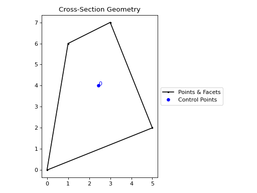
The following example creates a Geometry
object from an arbitrary four-sided shapely Polygon.
from shapely import Polygon
from sectionproperties.pre import Geometry

poly = Polygon([(0, 0), (5, 2), (3, 7), (1, 6)])
geom = Geometry(geom=poly)
geom.plot_geometry()
(Source code, png, hires.png, pdf)

Geometry object from a shapely polygon
CompoundGeometry objects consist of multiple
Geometry objects to form a complex region.
- CompoundGeometry.__init__(geoms: MultiPolygon | list[Geometry]) None[source]
Inits the CompoundGeometry class.
- Parameters:
geoms (MultiPolygon | list[Geometry]) – Either a list of Geometry objects or a
shapely.MultiPolygoninstance.
Example
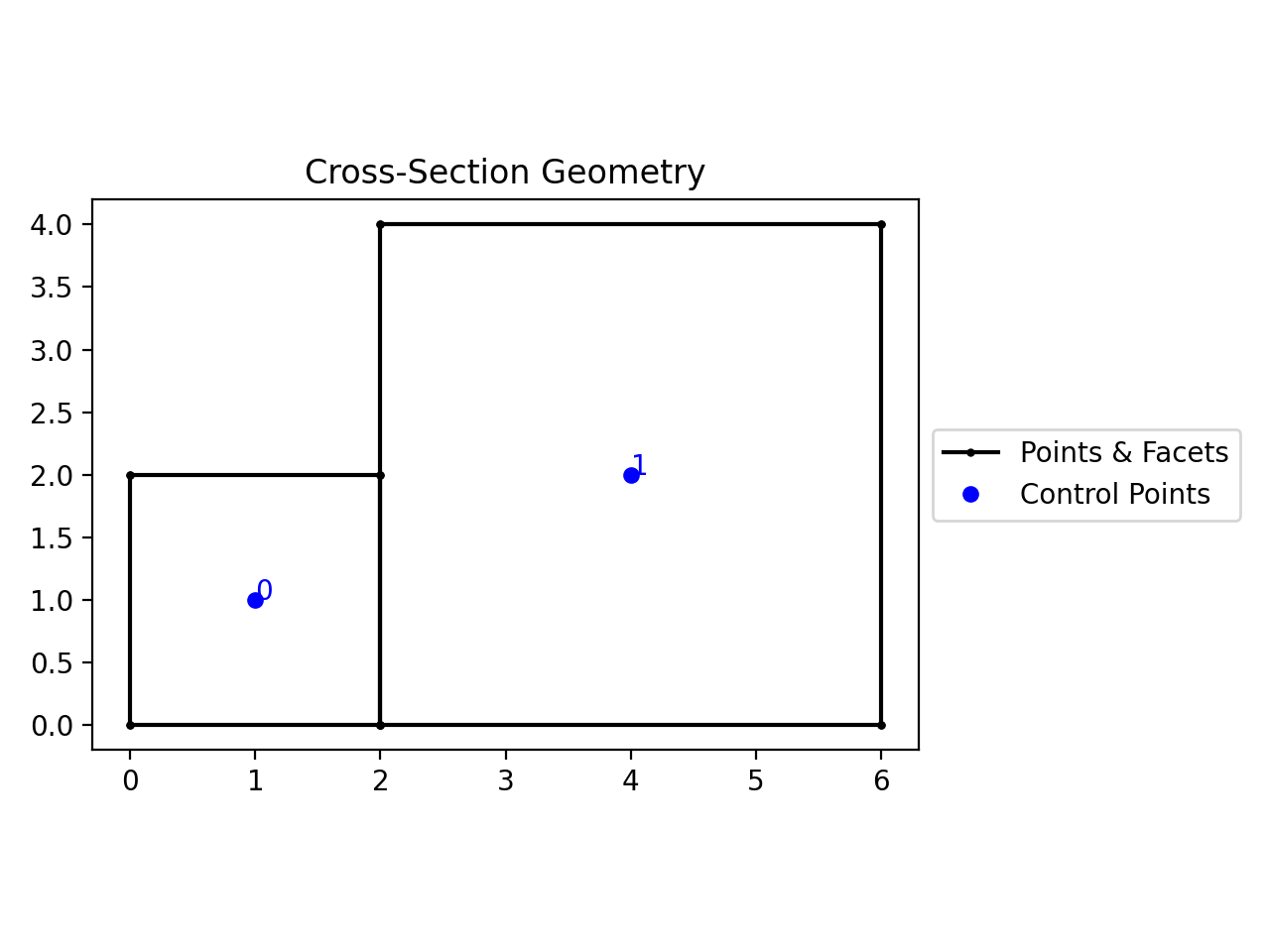
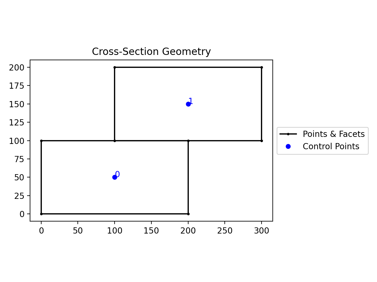
The following example creates a
CompoundGeometry object from two square
Geometry objects.
from shapely import Polygon
from sectionproperties.pre import Geometry, CompoundGeometry

sq1 = Polygon([(0, 0), (2, 0), (2, 2), (0, 2)])
sq2 = Polygon([(2, 0), (6, 0), (6, 4), (2, 4)])
geom_sq1 = Geometry(geom=sq1)
geom_sq2 = Geometry(geom=sq2)
geom = CompoundGeometry(geoms=[geom_sq1, geom_sq2])
geom.plot_geometry()
(Source code, png, hires.png, pdf)
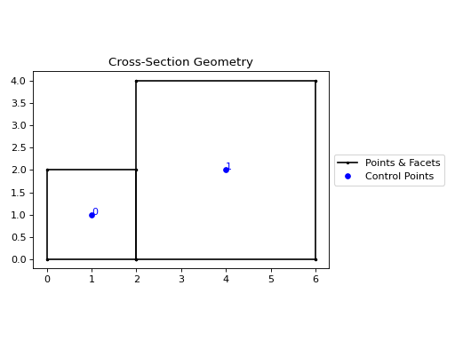
CompoundGeometry object from two shapely polygons
Cartesian Coordinates
In sectionproperties v1, geometries were created by specifying lists of
points, facets, holes, and control_points. This functionality has been
preserved as a legacy feature through the
sectionproperties.pre.geometry.Geometry.from_points() and
sectionproperties.pre.geometry.CompoundGeometry.from_points() class methods.
- static Geometry.from_points(points: list[tuple[float, float]], facets: list[tuple[int, int]], control_points: list[tuple[float, float]], holes: list[tuple[float, float]] | None = None, material: Material = Material(name='default', elastic_modulus=1, poissons_ratio=0, yield_strength=1, density=1, color='w')) Geometry[source]
Creates Geometry from points, facets, a control point and holes.
- Parameters:
points (list[tuple[float, float]]) – List of points (
x,y) defining the vertices of the section geometry. If the geometry simply contains a continuous list of exterior points, consider creating ashapely.Polygonobject (only requiring points), and create aGeometryobject using the constructor.facets (list[tuple[int, int]]) – A list of (
start,end) indices of vertices defining the edges of the section geoemtry. Can be used to define both external and internal perimeters of holes. Facets are assumed to be described in the order of exterior perimeter, interior perimeter 1, interior perimeter 2, etc.control_points (list[tuple[float, float]]) – An (
x,y) coordinate that describes the distinct, contiguous, region of a single material within the geometry. Must be entered as a list of coordinates, e.g. [(0.5, 3.2)]. Exactly one point is required for each geometry with a distinct material. If there are multiple distinct regions, then usesectionproperties.pre.geometry.CompoundGeometry.from_points()holes (list[tuple[float, float]] | None) – A list of points (
x,y) that define interior regions as being holes or voids. The point can be located anywhere within the hole region. Only one point is required per hole region. Defaults toNone.material (Material) – A
Materialobject that is to be assigned. Defaults topre.DEFAULT_MATERIAL.
- Raises:
ValueError – If there is not exactly one control point specified
RuntimeError – If geometry generation failed
- Returns:
Geometry object
- Return type:
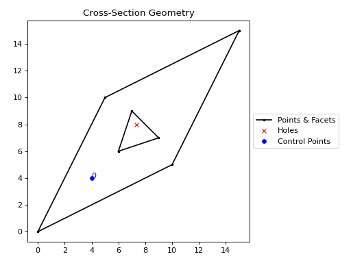
Example
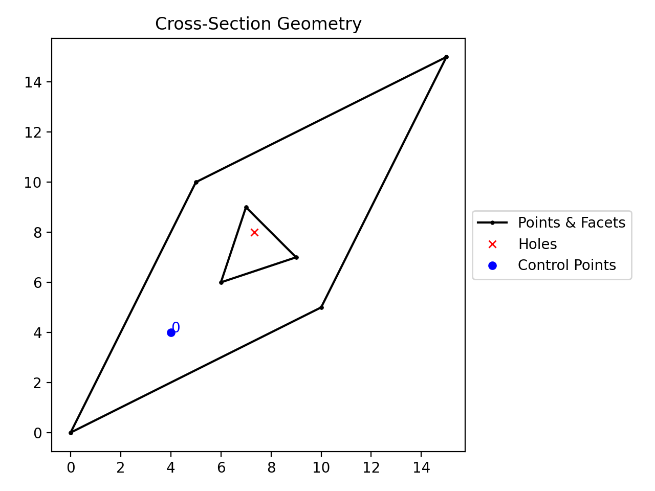
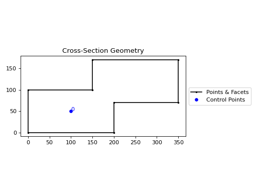
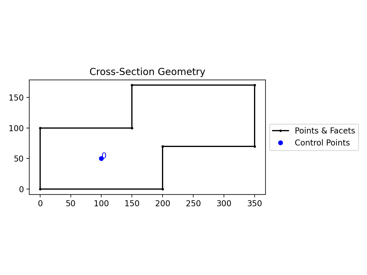
from sectionproperties.pre import Geometry

points = [(0, 0), (10, 5), (15, 15), (5, 10), (6, 6), (9, 7), (7, 9)]
facets = [(0, 1), (1, 2), (2, 3), (3, 0), (4, 5), (5, 6), (6, 4)]
control_points = [(4, 4)]
holes = [(7, 7)]

Geometry.from_points(
    points=points,
    facets=facets,
    control_points=control_points,
    holes=holes,
).plot_geometry()
(
Source code,png,hires.png,pdf)
Geometry created from points, facets and holes.
- static CompoundGeometry.from_points(points: list[tuple[float, float]], facets: list[tuple[int, int]], control_points: list[tuple[float, float]], holes: list[tuple[float, float]] | None = None, materials: list[Material] | None = None) CompoundGeometry[source]
Creates CompoundGeometry from points, facets, control points and holes.
An interface for the creation of CompoundGeometry objects through the definition of points, facets, control points and holes. Geometries created through this method are expected to be non-ambiguous meaning that no “overlapping” geometries exists and that nodal connectivity is maintained (e.g. there are no nodes “overlapping” with facets without nodal connectivity).
- Parameters:
points (list[tuple[float, float]]) – List of points (
x,y) defining the vertices of the section geometry.facets (list[tuple[int, int]]) – A list of (
start,end) indices of vertices defining the edges of the section geoemtry. Can be used to define both external and internal perimeters of holes. Facets are assumed to be described in the order of exterior perimeter, interior perimeter 1, interior perimeter 2, etc.control_points (list[tuple[float, float]]) – A list of points (
x,y) that define regions as being distinct, contiguous, and having one material. The point can be located anywhere within region. Only one point is permitted per region. The order ofcontrol_pointsmust be given in the same order as the order that polygons are created byfacets.holes (list[tuple[float, float]] | None) – A list of points (
x,y) that define interior regions as being holes or voids. The point can be located anywhere within the hole region. Only one point is required per hole region. Defaults toNone.materials (list[Material] | None) – A list of
Materialobjects that are to be assigned, in order, to the regions defined by the givencontrol_points. If not given, then theDEFAULT_MATERIALwill be used for each region. Defaults toNone.
- Raises:
ValueError – If there are materials provided without control points
ValueError – If the number of materials does not equal the number of control points
ValueError – If the number of exterior regions doesn’t match the number of control points
ValueError – If control points are not contained within geometries with holes
- Returns:
CompoundGeometry object from points
- Return type:
Example
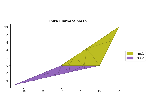
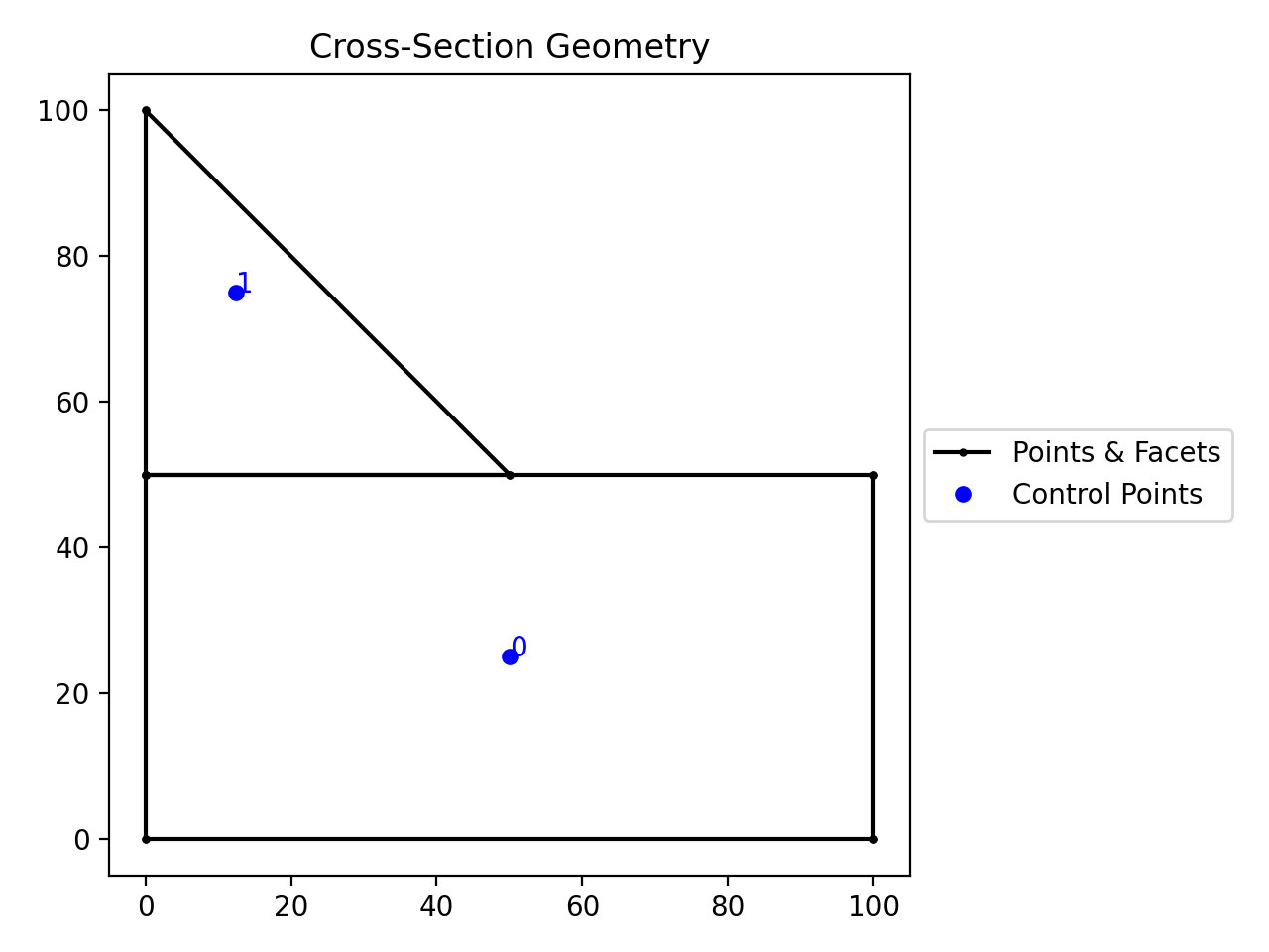
This example creates two regions with different material properties:
from sectionproperties.pre import Material, CompoundGeometry
from sectionproperties.analysis import Section

mat1 = Material(
    name="mat1",
    elastic_modulus=1.0,
    poissons_ratio=0.0,
    density=1.0,
    yield_strength=1.0,
    color="tab:olive",
)

mat2 = Material(
    name="mat2",
    elastic_modulus=2.0,
    poissons_ratio=0.0,
    density=2.0,
    yield_strength=2.0,
    color="tab:purple",
)

points = [(0, 0), (10, 0), (15, 10), (-12, -5)]
facets = [(0, 1), (1, 2), (2, 0), (1, 3), (3, 0), (0, 1)]
control_points = [(1, 1), (1, -1)]
materials = [mat1, mat2]

geom = CompoundGeometry.from_points(
    points=points,
    facets=facets,
    control_points=control_points,
    materials=materials,
)
geom.create_mesh(mesh_sizes=[0])
Section(geometry=geom).plot_mesh()
(
Source code,png,hires.png,pdf)
Composite CompoundGeometry created from points and facets.
CAD Files
Various CAD files can be imported to creating sectionproperties geometries.
sectionproperties currently supports the following formats:
Drawing Exchange Format -
.dxfRhino 3D Model Format -
.3dmRhino BREP Encoding
Note
The dependencies used to import CAD files are not included by default in the base
installation. To install sectionproperties with CAD import functionality, use
the dxf and/or rhino options:
pip install sectionproperties[dxf]
pip install sectionproperties[rhino]
.dxf
Geometry objects can be created from .dxf
files using the
sectionproperties.pre.geometry.Geometry.from_dxf() method.
- static Geometry.from_dxf(dxf_filepath: str | Path, spline_delta: float = 0.1, degrees_per_segment: float = 1.0) Geometry | CompoundGeometry[source]
An interface for the creation of Geometry objects from CAD .dxf files.
- Parameters:
dxf_filepath (str | Path) – A path-like object for the dxf file
spline_delta (float) – Splines are not supported in
shapely, so they are approximated as polylines, this argument affects the spline sampling rate. Defaults to0.1.degrees_per_segment (float) – The number of degrees discretised as a single line segment. Defaults to
1.0.
- Returns:
Geometry or CompoundGeometry object
- Return type:
Example
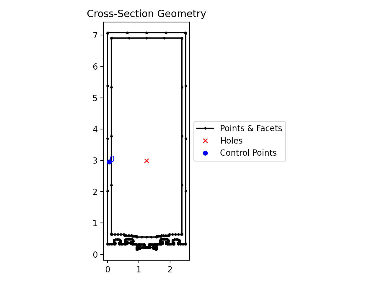
The following example loads a .dxf file and creates a
Geometry object from its contents.
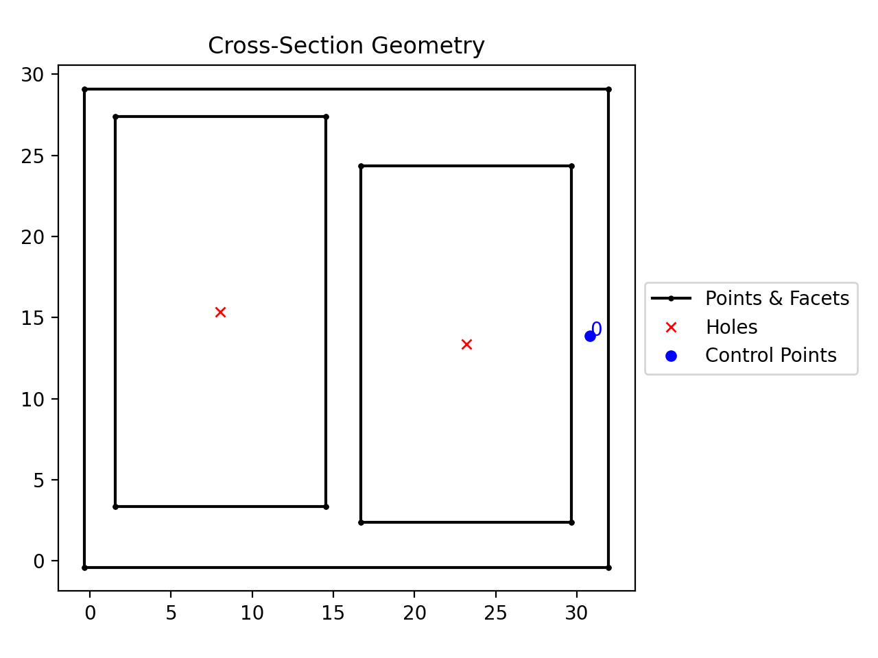
from sectionproperties.pre import Geometry

# the following path is a .dxf file that describes a box section with two holes
dxf_path = "../_static/cad_files/box_section.dxf"

# load dxf file into a Geometry object
geom = Geometry.from_dxf(dxf_filepath=dxf_path)
geom.plot_geometry()
(Source code, png, hires.png, pdf)
Geometry object from a .dxf file
Note
Loading multiple regions from a single .dxf file into a CompoundGeometry is
not currently supported in sectionproperties. A possible work around involves
saving each region as a separate .dxf file, importing each region individually
using Geometry.from_dxf(), then combining the regions using the + operator.
Rhino
Geometry objects can be created from .3dm
files and BREP encodings. Various limitations and assumptions need to be acknowledged:
Cross-section analysis is 2D and Rhino is a 3D environment.
The recognised Rhino geometries are limited to planer-single-surfaced BREPs.
Rhino uses NURBS for surface boundaries and
sectionpropertiesuses piecewise linear boundaries.A search plane is defined.
See the keyword arguments below that are used to search and simplify the Rhino geometry.
Rhino files are read via the class methods
sectionproperties.pre.geometry.Geometry.from_3dm() and
sectionproperties.pre.geometry.CompoundGeometry.from_3dm(). Each class method
returns the respective objects.
- classmethod Geometry.from_3dm(filepath: str | Path, **kwargs: Any) Geometry[source]
Creates a Geometry object from a Rhino
.3dmfile.- Parameters:
- Keyword Arguments:
refine_num (Optional[int]) – Bézier curve interpolation number. In Rhino a surface’s edges are nurb based curves. Shapely does not support nurbs, so the individual Bézier curves are interpolated using straight lines. This parameter sets the number of straight lines used in the interpolation. Default is 1.
vec1 (Optional[numpy.ndarray]) – A 3d vector in the Shapely plane. Rhino is a 3D geometry environment. Shapely is a 2D geometric library. Thus a 2D plane needs to be defined in Rhino that represents the Shapely coordinate system.
vec1represents the 1st vector of this plane. It will be used as Shapely’s x direction. Default is [1,0,0].vec2 (Optional[numpy.ndarray]) – Continuing from
vec1,vec2is another vector to define the Shapely plane. It must not be [0,0,0] and it’s only requirement is that it is any vector in the Shapely plane (but not equal tovec1). Default is [0,1,0].plane_distance (Optional[float]) – The distance to the Shapely plane. Default is 0.
project (Optional[bool]) – Controls if the breps are projected onto the plane in the direction of the Shapley plane’s normal. Default is True.
parallel (Optional[bool]) – Controls if only the rhino surfaces that have the same normal as the Shapely plane are yielded. If true, all non parallel surfaces are filtered out. Default is False.
- Raises:
RuntimeError – A RuntimeError is raised if two or more polygons are found. This is dependent on the keyword arguments. Try adjusting the keyword arguments if this error is raised.
ImportError – If
rhino3dmis not installed. To enable rhino features usepip install sectionproperties[rhino].
- Returns:
A Geometry object.
- Return type:
Example
The following example loads a .3dm file and creates a
Geometry object from its contents.
from sectionproperties.pre import Geometry

# the following path is a .3dm file that describes a glazing section
rhino_path = "../_static/cad_files/rhino.3dm"

# load 3dm file into a Geometry object
geom = Geometry.from_3dm(filepath=rhino_path)
geom.plot_geometry()
(Source code, png, hires.png, pdf)
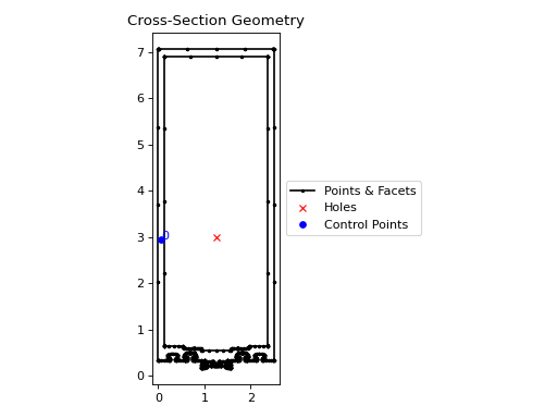
Geometry object from a .3dm file
- classmethod CompoundGeometry.from_3dm(filepath: str | Path, **kwargs: Any) CompoundGeometry[source]
Creates a CompoundGeometry object from the objects in a Rhino
3dmfile.- Parameters:
- Keyword Arguments:
refine_num (Optional[int]) – Bézier curve interpolation number. In Rhino a surface’s edges are nurb based curves. Shapely does not support nurbs, so the individual Bézier curves are interpolated using straight lines. This parameter sets the number of straight lines used in the interpolation. Default is 1.
vec1 (Optional[numpy.ndarray]) – A 3d vector in the Shapely plane. Rhino is a 3D geometry environment. Shapely is a 2D geometric library. Thus a 2D plane needs to be defined in Rhino that represents the Shapely coordinate system.
vec1represents the 1st vector of this plane. It will be used as Shapely’s x direction. Default is [1,0,0].vec2 (Optional[numpy.ndarray]) – Continuing from
vec1,vec2is another vector to define the Shapely plane. It must not be [0,0,0] and it’s only requirement is that it is any vector in the Shapely plane (but not equal tovec1). Default is [0,1,0].plane_distance (Optional[float]) – The distance to the Shapely plane. Default is 0.
project (Optional[bool]) – Controls if the breps are projected onto the plane in the direction of the Shapley plane’s normal. Default is True.
parallel (Optional[bool]) – Controls if only the rhino surfaces that have the same normal as the Shapely plane are yielded. If true, all non parallel surfaces are filtered out. Default is False.
- Raises:
ImportError – If
rhino3dmis not installed. To enable rhino features usepip install sectionproperties[rhino].- Returns:
CompoundGeometry object
- Return type:
Example
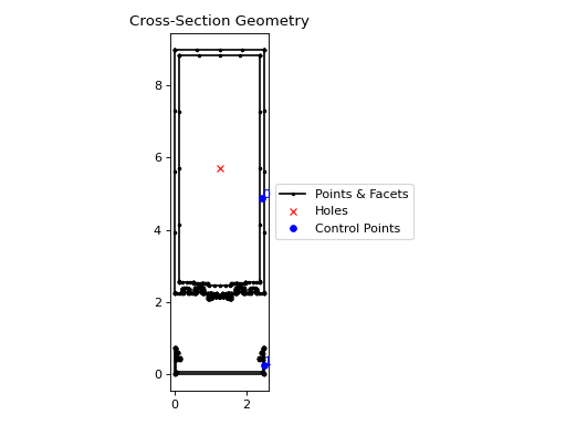
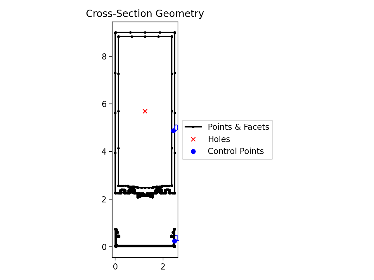
The following example loads a .3dm file and creates a
CompoundGeometry object from its contents.
from sectionproperties.pre import CompoundGeometry

# the following path is a .3dm file that describes two distinct 2D surfaces
rhino_path = "../_static/cad_files/rhino_compound.3dm"

# load 3dm file into a CompoundGeometry object
geom = CompoundGeometry.from_3dm(filepath=rhino_path)
geom.plot_geometry()
(Source code, png, hires.png, pdf)

CompoundGeometry object from a .3dm file
Geometry objects can also be created from
encodings of Rhino BREP.
- classmethod Geometry.from_rhino_encoding(r3dm_brep: str, **kwargs: Any) Geometry[source]
Load an encoded single surface planer brep.
- Parameters:
- Keyword Arguments:
refine_num (Optional[int]) – Bézier curve interpolation number. In Rhino a surface’s edges are nurb based curves. Shapely does not support nurbs, so the individual Bézier curves are interpolated using straight lines. This parameter sets the number of straight lines used in the interpolation. Default is 1.
vec1 (Optional[numpy.ndarray]) – A 3d vector in the Shapely plane. Rhino is a 3D geometry environment. Shapely is a 2D geometric library. Thus a 2D plane needs to be defined in Rhino that represents the Shapely coordinate system.
vec1represents the 1st vector of this plane. It will be used as Shapely’s x direction. Default is [1,0,0].vec2 (Optional[numpy.ndarray]) – Continuing from
vec1,vec2is another vector to define the Shapely plane. It must not be [0,0,0] and it’s only requirement is that it is any vector in the Shapely plane (but not equal tovec1). Default is [0,1,0].plane_distance (Optional[float]) – The distance to the Shapely plane. Default is 0.
project (Optional[bool]) – Controls if the breps are projected onto the plane in the direction of the Shapley plane’s normal. Default is True.
parallel (Optional[bool]) – Controls if only the rhino surfaces that have the same normal as the Shapely plane are yielded. If true, all non parallel surfaces are filtered out. Default is False.
- Raises:
ImportError – If
rhino3dmis not installed. To enable rhino features usepip install sectionproperties[rhino].- Returns:
A Geometry object found in the encoded string.
- Return type:
Example
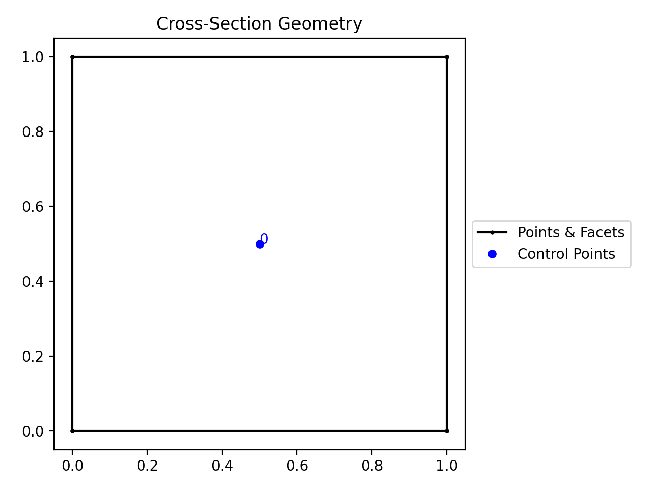
The following example loads a .json file describing a Rhino BREP and creates a
Geometry object from its contents.
import json
from sectionproperties.pre import Geometry

# the following path is a .json file that is a BREP describing a 1 x 1 square
rhino_path = "../_static/cad_files/rhino_brep.json"

with open(rhino_path) as rhino_file:
    brep_encoded = json.load(rhino_file)

# load BREP file into a Geometry object
geom = Geometry.from_rhino_encoding(r3dm_brep=brep_encoded)
geom.plot_geometry()
(Source code, png, hires.png, pdf)
Geometry object from a Rhino BREP file
More advanced filtering can be achieved by working with the Shapely geometries directly.
These can be accessed by load_3dm() and
load_brep_encoding().
Section Library
In order to make your life easier, there are a number of built-in functions that
generate typical structural cross-sections, resulting in
Geometry or
CompoundGeometry objects. These typical
cross-sections reside in the sectionproperties.pre.library module.
Primitive Sections
Constructs a rectangular section. |
|
Constructs a circular section. |
|
Constructs a circular section defined by its area. |
|
Constructs an elliptical section. |
|
Constructs a triangular section. |
|
Constructs a triangular section with a radius. |
|
Constructs a cruciform section. |
Steel Sections
Constructs a circular hollow section (CHS). |
|
Constructs an elliptical hollow section (EHS). |
|
Constructs a rectangular hollow section (RHS). |
|
Constructs a regular hollow polygon section. |
|
Constructs an I section. |
|
Constructs a monosymmetric I section. |
|
Constructs a tapered flange I section. |
|
Constructs a parallel flange channel (PFC). |
|
Constructs a tapered flange channel section. |
|
Constructs a tee section. |
|
Constructs an angle section. |
|
Constructs a cee section. |
|
Constructs a zed section. |
|
Constructs a box girder section. |
|
Constructs a bulb section. |
Concrete Sections
Constructs a reinforced concrete rectangular section. |
|
Constructs a reinforced concrete column section. |
|
Constructs a reinforced concrete tee section. |
|
Constructs a reinforced concrete circular section. |
|
Constructs a reinforced concrete rectangular wall section. |
|
Constructs a reinforced concrete cee-shaped wall section. |
|
Constructs a reinforced concrete tee-shaped wall section. |
|
Constructs a reinforced concrete single lift core section. |
|
Constructs a reinforced concrete double lift core (type A) section. |
|
Constructs a reinforced concrete double lift core (type B) section. |
|
Constructs a reinforced concrete stairwell section. |
Timber Section
Constructs a CLT rectangular section. |
Bridge Sections
Constructs a super T girder section to AS5100.5. |
|
Constructs a precast I girder section to AS5100.5. |
NASTRAN Sections
Constructs a BAR section. |
|
Constructs a BOX section. |
|
Constructs a BOX1 section. |
|
Constructs a CHAN section. |
|
Constructs a CHAN1 section. |
|
Constructs a CHAN2 section. |
|
Constructs Nastran's cruciform section. |
|
Constructs a flanged cruciform section. |
|
Constructs a DBOX section. |
|
Constructs a GBOX section. |
|
Constructs a H section. |
|
Constructs a HAT section. |
|
Constructs a HAT1 section. |
|
Constructs a HEXA section. |
|
Constructs Nastran's I section. |
|
Constructs an I1 section. |
|
Constructs an L section. |
|
Constructs a circular rod section. |
|
Constructs a T section. |
|
Constructs a T1 section. |
|
Constructs a T2 section. |
|
Constructs a circular tube section. |
|
Constructs a circular TUBE2 section. |
|
Constructs a Z section. |
Manipulating Geometry Objects
Geometries in sectionproperties are able to be manipulated in 2D space for the
purpose of creating novel, custom section geometries that the user may require.
Note
Operations on geometries are non-destructive. For each operation, a new geometry object is returned.
This gives sectionproperties geometries a fluent API, meaning that
transformation methods can be chained together, see
Advanced Geometry Creation for
further examples.
Align
There are two available align methods:
align_to()- aligns one geometry to another on a specified side.align_center()- aligns the center of one geometry to either the center of another, or a specific point.
- Geometry.align_to(other: Geometry | CompoundGeometry | tuple[float, float], on: str, inner: bool = False) Geometry[source]
Aligns the geometry to another Geometry object.
Returns a new Geometry object, representing
selftranslated so that is alignedonone of the outer bounding box edges ofother.If
otheris a tuple representing an (x,y) coordinate, then the new Geometry object will represent ‘self’ translated so that it is alignedonthat side of the point.- Parameters:
other (Geometry | CompoundGeometry | tuple[float, float]) – Either another Geometry or a tuple representing an (
x,y) coordinate point thatselfshould align to.on (str) – A str of either “left”, “right”, “bottom”, or “top” indicating which side of
otherthatselfshould be aligned to.inner (bool) – If True, align
selftootherin such a way thatselfis aligned to the “inside” ofother. In other words, alignselftootheron the specified edge so they overlap. Defaults toFalse.
- Returns:
Geometry object translated to alignment location
- Return type:
Example
from sectionproperties.pre.library import rectangular_section
from sectionproperties.pre.library import triangular_section

rect = rectangular_section(b=100, d=50)
tri = triangular_section(b=50, h=50)
tri = tri.align_to(other=rect, on="top")
(rect + tri).plot_geometry()
(
Source code,png,hires.png,pdf)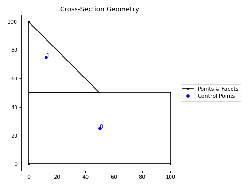
A triangle aligned to the top of a rectangle.
- Geometry.align_center(align_to: Geometry | tuple[float, float] | None = None) Geometry[source]
Aligns the geometry to a center point.
Returns a new Geometry object, translated in both
xandy, so that the the new object’s centroid will be aligned with the centroid of the object inalign_to. Ifalign_tois an (x,y) coordinate, then the centroid will be aligned to the coordinate. Ifalign_toisNonethen the new object will be aligned with its centroid at the origin.- Parameters:
align_to (Geometry | tuple[float, float] | None) – Another Geometry to align to, an (
x,y) coordinate orNone. Defaults toNone.- Raises:
ValueError –
align_tois not valid- Returns:
Geometry object translated to new alignment
- Return type:
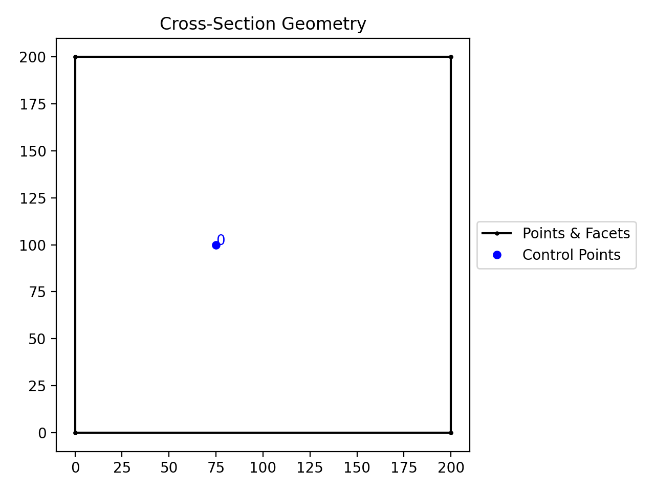
Example
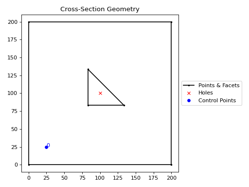
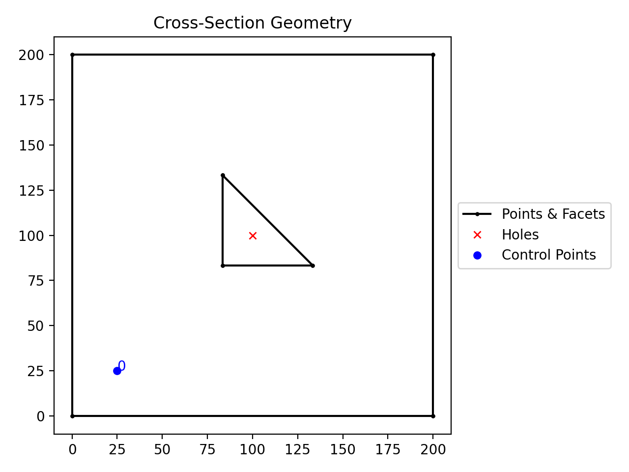
from sectionproperties.pre.library import rectangular_section
from sectionproperties.pre.library import triangular_section

rect = rectangular_section(b=200, d=200)
tri = triangular_section(b=50, h=50)
tri = tri.align_center(align_to=rect)
geom = rect + tri
geom.holes = [(100, 100)]
geom.control_points = [(25, 25)]
geom.plot_geometry()
(
Source code,png,hires.png,pdf)
A triangular hole aligned to the centre of a square.
- CompoundGeometry.align_center(align_to: Geometry | tuple[float, float] | None = None) CompoundGeometry[source]
Aligns the CompoundGeometry to a center point.
Returns a new CompoundGeometry object, translated in both
xandy, so that the center-point of the new object’s material-weighted centroid will be aligned with centroid of the object inalign_to. Ifalign_tois anx,ycoordinate, then the centroid will be aligned to the coordinate. Ifalign_tois None then the new object will be aligned with its centroid at the origin.Note
The material-weighted centroid refers to when individual geometries within the
CompoundGeometryobject have been assigned differing materials. The centroid of the compound geometry is calculated by using the elastic modulus of each geometry’s assigned material.- Parameters:
align_to (Geometry | tuple[float, float] | None) – Another Geometry to align to, an (
x,y) coordinate, orNone. Defaults toNone.- Raises:
ValueError –
align_tois not valid- Returns:
CompoundGeometry object translated to new alignment
- Return type:
Example
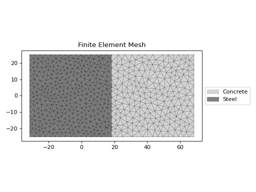
The following example creates a rectanglular steel-concrete composite section and uses the
align_center()method to place the composite centroid at the origin.from sectionproperties.pre import Material from sectionproperties.pre.library import rectangular_section from sectionproperties.analysis import Section steel = Material( name="Steel", elastic_modulus=200e3, poissons_ratio=0.3, density=7.85e-6, yield_strength=250, color="grey", ) concrete = Material( name="Concrete", elastic_modulus=30.1e3, poissons_ratio=0.2, density=2.4e-6, yield_strength=32, color="lightgrey", ) geom_steel = rectangular_section(d=50, b=50, material=steel) geom_timber = rectangular_section(d=50, b=50, material=concrete) geom = geom_timber.align_to(geom_steel, on="right") + geom_steel geom = geom.align_center() geom.create_mesh(mesh_sizes=[10, 5]) Section(geometry=geom).plot_mesh()
(
Source code,png,hires.png,pdf)
Reinforced 200PFC mirrored.
Mirror
Geometry can be mirrored about a specified point on either the x or y axis.
- Geometry.mirror_section(axis: str = 'x', mirror_point: tuple[float, float] | str = 'center') Geometry[source]
Mirrors the geometry about a point on either the x or y-axis.
- Parameters:
- Returns:
New Geometry object mirrored on
axisaboutmirror_point- Return type:
Example
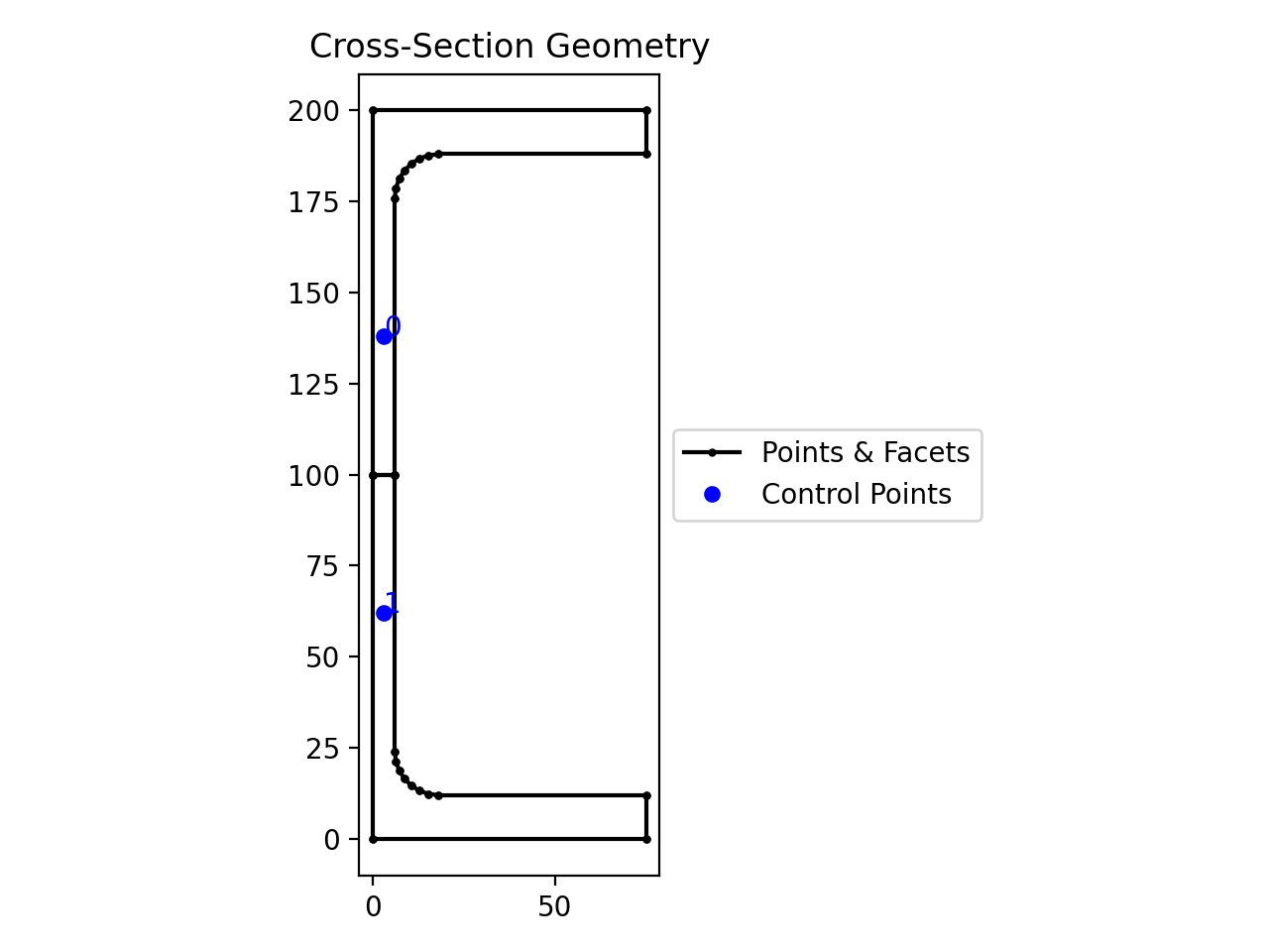
The following example mirrors a 200PFC section about the y-axis:
from sectionproperties.pre.library import channel_section

geom = channel_section(d=200, b=75, t_f=12, t_w=6, r=12, n_r=8)
geom.mirror_section(axis="y", mirror_point=(0, 0)).plot_geometry()
(
Source code,png,hires.png,pdf)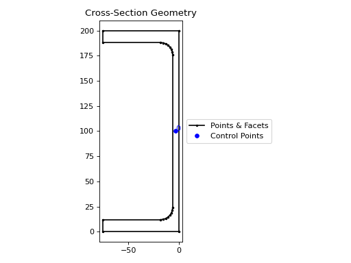
A 200PFC section mirrored about the y-axis and the point
(0, 0)
Rotate
Geometry can be rotated by any angle about a point.
- Geometry.rotate_section(angle: float, rot_point: tuple[float, float] | str = 'center', use_radians: bool = False) Geometry[source]
Rotate the Geometry object.
Rotates the geometry and specified angle about a point. If the rotation point is not provided, rotates the section about the center of the geometry’s bounding box.
- Parameters:
angle (float) – Angle (degrees by default) by which to rotate the section. A positive angle leads to a counter-clockwise rotation.
rot_point (tuple[float, float] | str) – Point (
x,y) about which to rotate the section. If not provided, will rotate about the “center” of the geometry’s bounding box. Defaults to"center".use_radians (bool) – Boolean to indicate whether
angleis in degrees or radians. If True,angleis interpreted as radians. Defaults toFalse.
- Returns:
New Geometry object rotated by
angleaboutrot_point- Return type:
Example
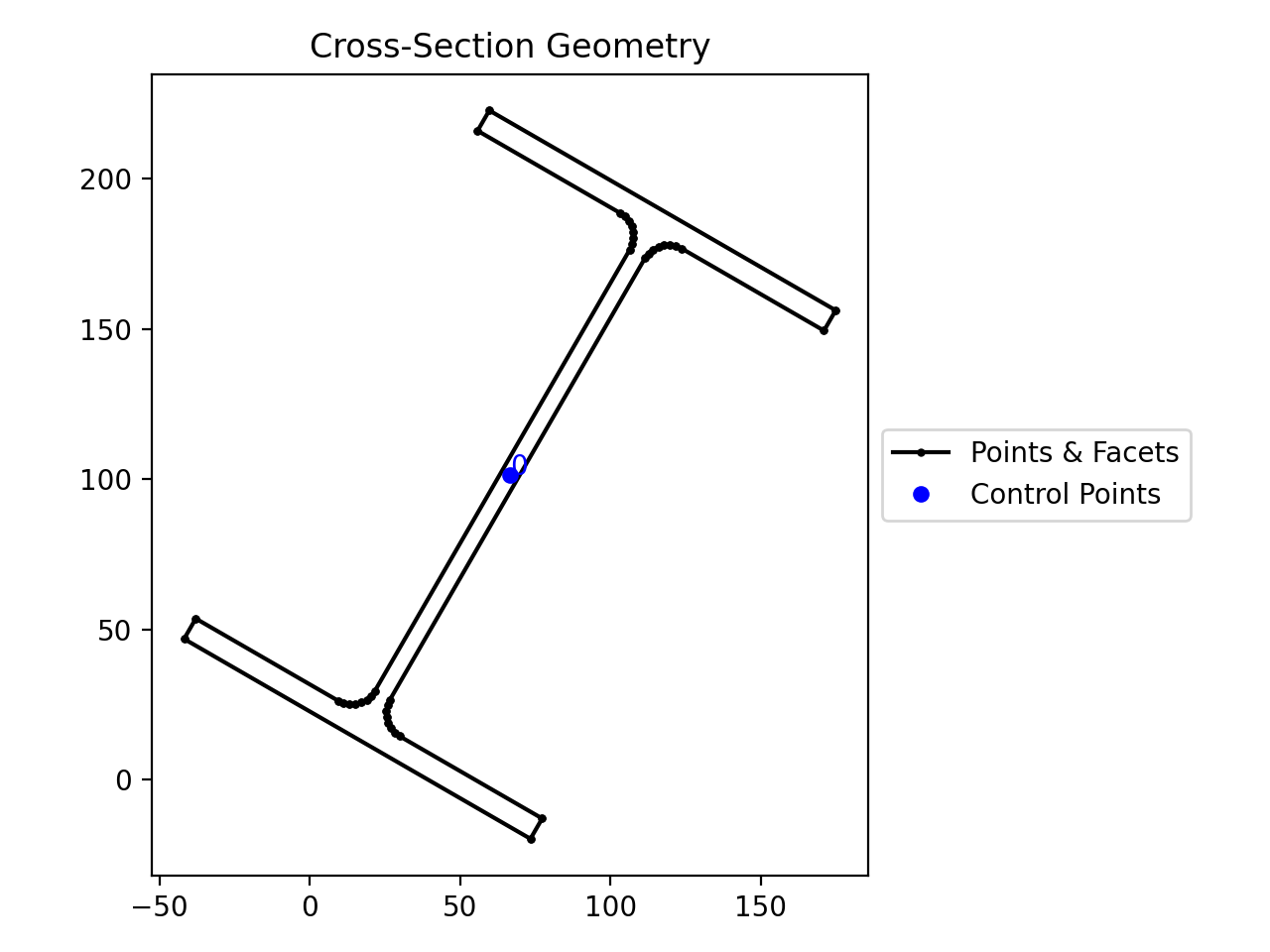
from sectionproperties.pre.library import i_section

geom = i_section(d=203, b=133, t_f=7.8, t_w=5.8, r=8.9, n_r=8)
geom.rotate_section(angle=-30).plot_geometry()
(
Source code,png,hires.png,pdf)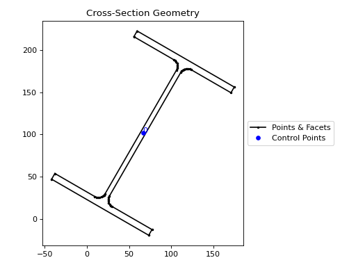
A 200UB25 section rotated clockwise by 30 degrees
Shift
There are two available shift methods:
shift_section()- shifts the entire geometry by a vector.shift_points()- shifts specific points within the geometry by either a vector, or to an absolute location.
- Geometry.shift_section(x_offset: float = 0.0, y_offset: float = 0.0) Geometry[source]
Returns a new Geometry object translated by (
x_offset,y_offset).- Parameters:
- Returns:
New Geometry object shifted by
x_offsetandy_offset- Return type:
Example
from sectionproperties.pre.library import rectangular_section

rect1 = rectangular_section(b=200, d=100)
rect2 = rect1.shift_section(x_offset=100, y_offset=100)
(rect1 + rect2).plot_geometry()
(
Source code,png,hires.png,pdf)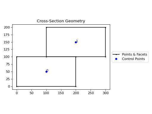
Using
shift_sectionto shift geometry.
- Geometry.shift_points(point_idxs: int | list[int], dx: float = 0.0, dy: float = 0.0, abs_x: float | None = None, abs_y: float | None = None) Geometry[source]
Shifts the points in the geometry.
Translates one (or many points) in the geometry by either a relative amount or to a new absolute location. Returns a new Geometry representing the original with the selected point(s) shifted to the new location.
Points are identified by their index, their relative location within the points list found in
self.points. You can callself.plot_geometry(labels="points")to see a plot with the points labeled to find the appropriate point indexes.- Parameters:
point_idxs (int | list[int]) – An integer representing an index location or a list of integer index locations.
dx (float) – The number of units in the x-direction to shift the point(s) by. Defaults to
0.0.dy (float) – The number of units in the y-direction to shift the point(s) by. Defaults to
0.0.abs_x (float | None) – Absolute x-coordinate in coordinate system to shift the point(s) to. If
abs_xis provided,dxis ignored. If providing a list topoint_idxs, all points will be moved to this absolute location. Defaults toNone.abs_y (float | None) – Absolute y-coordinate in coordinate system to shift the point(s) to. If
abs_yis provided,dyis ignored. If providing a list topoint_idxs, all points will be moved to this absolute location. Defaults toNone.
- Returns:
Geometry object with selected points translated to the new location
- Return type:
Example
The following example expands the sides of a rectangle, one point at a time, to make it a square:
from sectionproperties.pre.library import rectangular_section

geom = rectangular_section(d=200, b=150)

# using relative shifting
geom_step_1 = geom.shift_points(point_idxs=1, dx=50)

# using absolute relocation
geom_step_1.shift_points(point_idxs=2, abs_x=200).plot_geometry()
(
Source code,png,hires.png,pdf)
Rectangle transformed to a square with
shift_points
Split
Geometry can be split either side of a straight line.
- Geometry.split_section(point_i: tuple[float, float], point_j: tuple[float, float] | None = None, vector: tuple[float, float] | ndarray[tuple[Any, ...], dtype[float64]] | None = None) tuple[list[Geometry], list[Geometry]][source]
Splits geometry about a line.
Splits, or bisects, the geometry about a line, as defined by two points on the line or by one point on the line and a vector. Either
point_jorvectormust be given. Ifpoint_jis given,vectoris ignored.Returns a tuple of two lists each containing new Geometry instances representing the
"top"and"bottom"portions, respectively, of the bisected geometry.If the line is a vertical line then the
"right"and"left"portions, respectively, are returned.- Parameters:
point_i (tuple[float, float]) – A tuple of (
x,y) coordinates to define a first point on the linepoint_j (tuple[float, float] | None) – A tuple of (
x,y) coordinates to define a second point on the line. Defaults toNone.vector (tuple[float, float] | ndarray[tuple[Any, ...], dtype[float64]] | None) – A tuple or numpy array of (
x,y) components to define the line direction. Defaults toNone.
- Raises:
ValueError – Line definition is invalid
- Returns:
A tuple of lists containing Geometry objects that are bisected about the line defined by the two given points. The first item in the tuple represents the geometries on the
"top"of the line (or to the"right"of the line, if vertical) and the second item represents the geometries to the"bottom"of the line (or to the"left"of the line, if vertical).- Return type:
Example
The following example splits a 200PFC section about the x-axis at
y=100:from sectionproperties.pre.library import channel_section geom = channel_section(d=200, b=75, t_f=12, t_w=6, r=12, n_r=8) top_geoms, bot_geoms = geom.split_section( point_i=(0, 100), point_j=(1, 100), ) (top_geoms[0] + bot_geoms[0]).plot_geometry()
(
Source code,png,hires.png,pdf)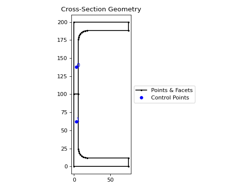
A 200PFC section split about the y-axis.
Offset
The external and/or internal perimeter of a geometry can be dilated or eroded by a set value.
- Geometry.offset_perimeter(amount: float = 0.0, where: str = 'exterior', resolution: int = 12) Geometry | CompoundGeometry[source]
Dilates or erodes the section perimeter by a discrete amount.
- Parameters:
amount (float) – Distance to offset the section by. A negative value “erodes” the section. A positive value “dilates” the section. Defaults to
0.0.where (str) – One of either
"exterior","interior", or"all"to specify which edges of the geometry to offset. If geometry has no interiors, then this parameter has no effect. Defaults to"exterior".resolution (int) – Number of segments used to approximate a quarter circle around a point. Defaults to
12.
- Raises:
ValueError –
whereis invalidValueError – Attempted to offset internally where there are no holes
RuntimeError – If geometry generation fails
- Returns:
Geometry object translated to new alignment
- Return type:
Example
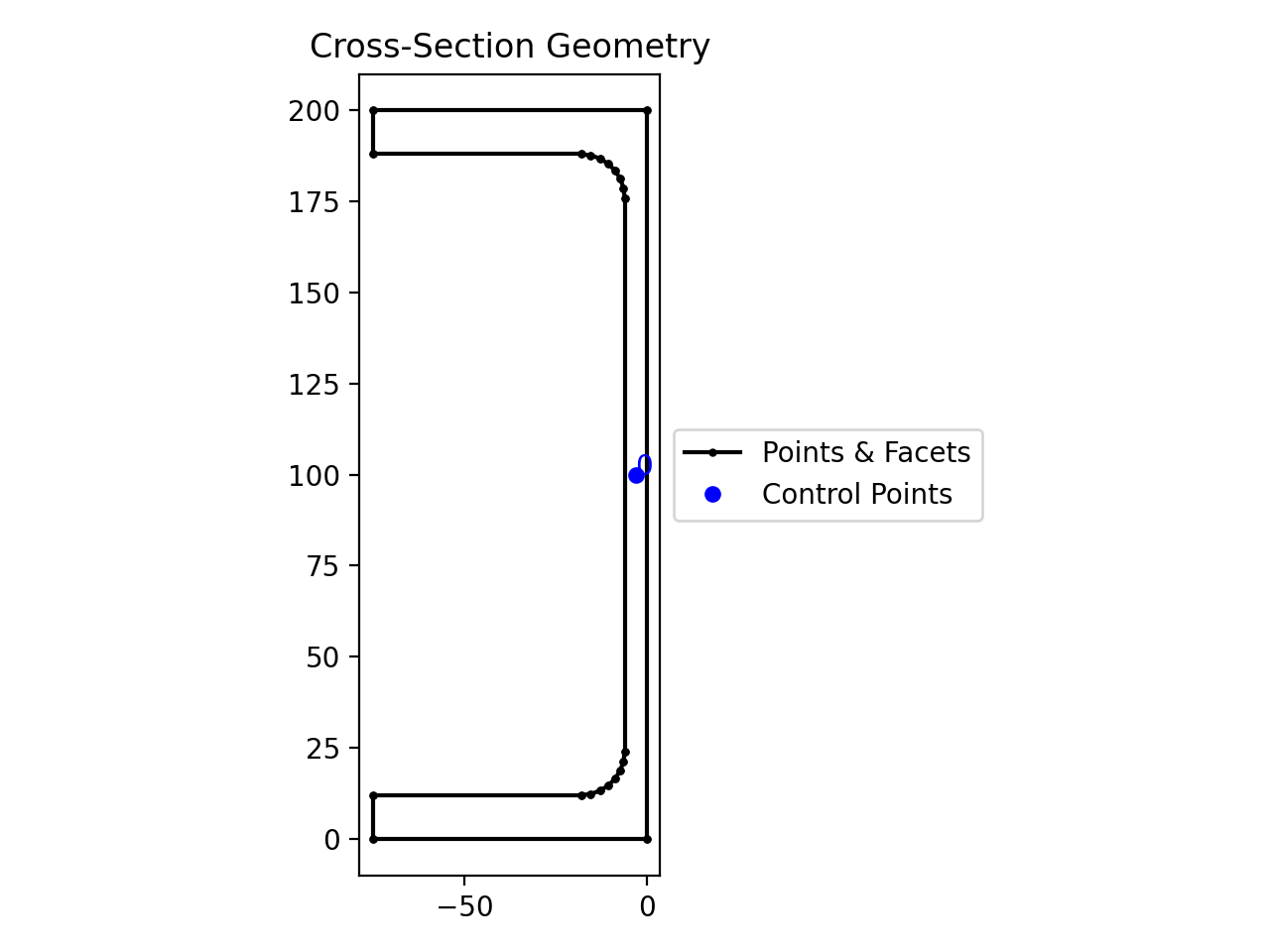
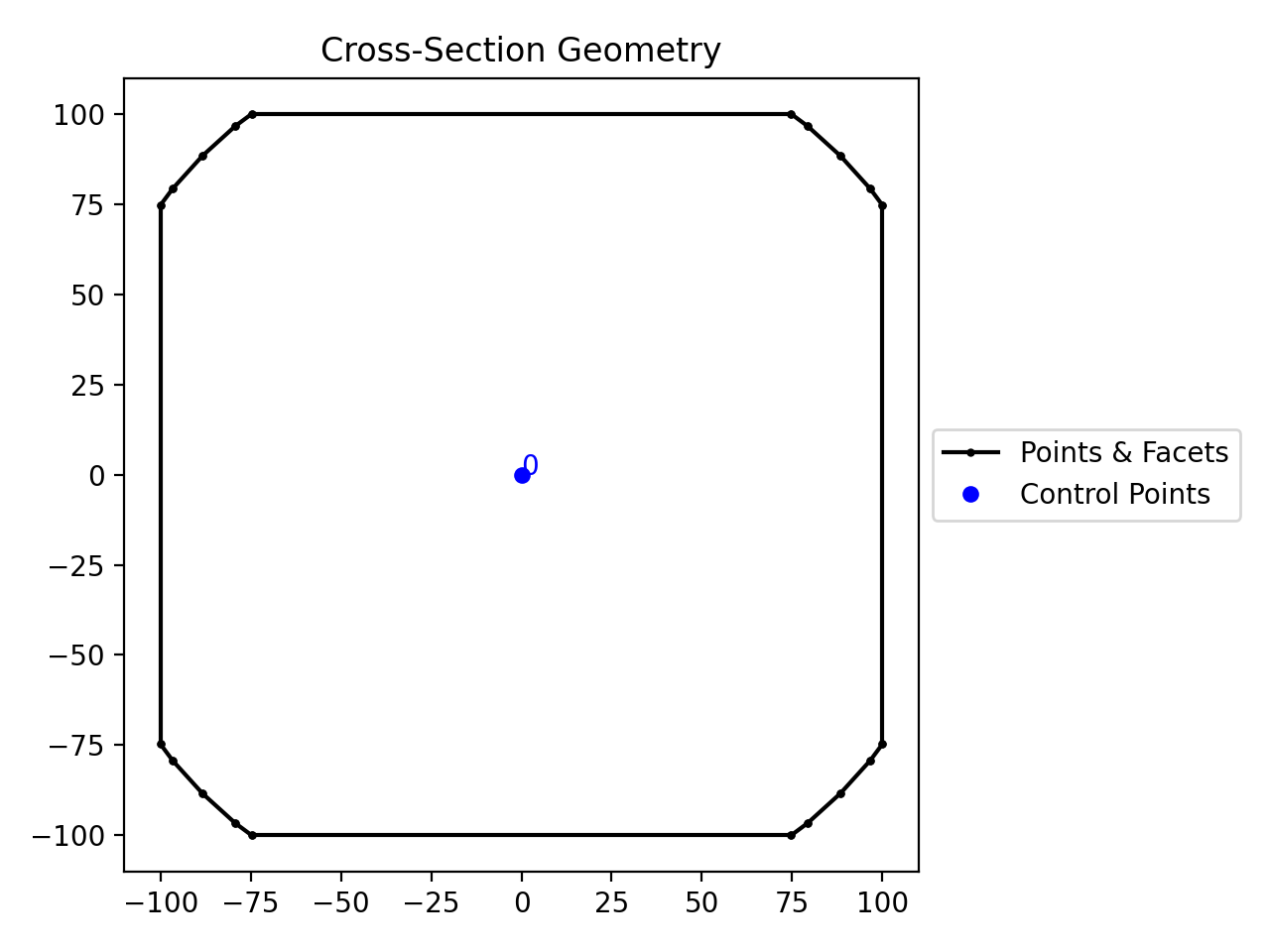
The following example erodes a 200PFC section by 2 mm:
from sectionproperties.pre.library import channel_section

geom = channel_section(d=200, b=75, t_f=12, t_w=6, r=12, n_r=8)
geom.offset_perimeter(amount=-2.0).plot_geometry()
(
Source code,png,hires.png,pdf)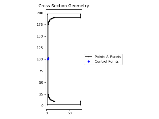
A 200PFC eroded by 2 mm.
- CompoundGeometry.offset_perimeter(amount: float = 0.0, where: str = 'exterior', resolution: int = 12) CompoundGeometry[source]
Dilates/erodes the perimeter of a CompoundGeometry object by an amount.
- Parameters:
amount (float) – Distance to offset the section by. A negative value “erodes” the section. A positive value “dilates” the section. Defaults to
0.0.where (str) – One of either
"exterior","interior", or"all"to specify which edges of the geometry to offset. If geometry has no interiors, then this parameter has no effect. Defaults to"exterior".resolution (int) – Number of segments used to approximate a quarter circle around a point. Defaults to
12.
- Returns:
CompoundGeometry object translated to new alignment
- Return type:
Example
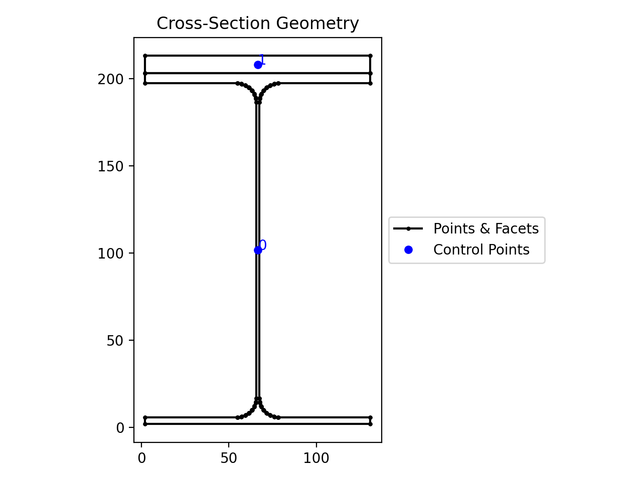
The following example erodes a 200UB25 with a 12 plate stiffener section by 2 mm:
from sectionproperties.pre.library import rectangular_section, i_section

geom1 = i_section(d=203, b=133, t_f=7.8, t_w=5.8, r=8.9, n_r=8)
geom2 = rectangular_section(d=12, b=133)
compound = geom1 + geom2.align_center(align_to=geom1).align_to(
    other=geom1, on="top"
)
compound.offset_perimeter(amount=-2).plot_geometry()
(
Source code,png,hires.png,pdf)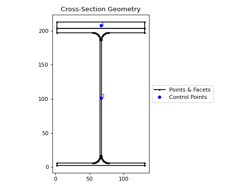
Eroded 200UB25 with stiffener.
Note
If performing a positive offset on a
CompoundGeometrywith multiple materials, ensure that the materials propagate as desired by performing a.plot_mesh()prior to performing any analysis.
Set Operations
Both Geometry and
CompoundGeometry objects can be manipulated
using Python’s set operators. See
Advanced Geometry Creation for further
examples using set operations.
| (Union)
- Geometry.__or__(other: Geometry | CompoundGeometry) Geometry | CompoundGeometry[source]
Performs a union on Geometry objects with the
|operator.- Parameters:
other (Geometry | CompoundGeometry) – Geometry object to perform the union with
- Raises:
ValueError – Unable to perform union
- Returns:
New Geometry object
- Return type:
Example
The following example combines two rectangles using the
|operator:from sectionproperties.pre.library import rectangular_section rect1 = rectangular_section(d=100, b=200) rect2 = rectangular_section(d=100, b=200).shift_section( x_offset=150, y_offset=70, ) (rect1 | rect2).plot_geometry()
(
Source code,png,hires.png,pdf)
Union of two rectangles
- (Subtraction)
- Geometry.__sub__(other: Geometry | CompoundGeometry) Geometry | CompoundGeometry[source]
Performs a difference operation on Geometry objects with the
-operator.Subtracts the second geometry from the first geometry.
- Parameters:
other (Geometry | CompoundGeometry) – Geometry object to perform the difference operation with
- Raises:
ValueError – Unable to perform difference
- Returns:
New Geometry object
- Return type:
Example
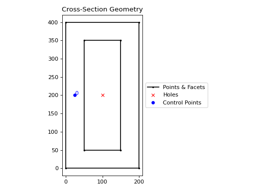
The following example creates a hollow box using the
-operator:from sectionproperties.pre.library import rectangular_section rect1 = rectangular_section(d=400, b=200) rect2 = rectangular_section(d=300, b=100).align_center(align_to=rect1) (rect1 - rect2).plot_geometry()
(
Source code,png,hires.png,pdf)
Hollow box
& (Intersection)
- Geometry.__and__(other: Geometry | CompoundGeometry) Geometry | CompoundGeometry[source]
Performs an intersection on Geometry objects with the
&operator.Returns the regions of geometry common to both geometries.
- Parameters:
other (Geometry | CompoundGeometry) – Geometry object to perform the intersection with
- Raises:
ValueError – Unable to perform intersection
- Returns:
New Geometry object
- Return type:
Example
The following example performs an intersection of a square and circle using the
&operator:from sectionproperties.pre.library import rectangular_section from sectionproperties.pre.library import circular_section rect = rectangular_section(d=200, b=200).align_center(align_to=(0, 0)) circle = circular_section(d=250, n=64) (rect & circle).plot_geometry()
(
Source code,png,hires.png,pdf)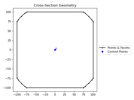
Intersection of a square and circle
^ (Symmetric Difference)
- Geometry.__xor__(other: Geometry | CompoundGeometry) Geometry | CompoundGeometry[source]
Performs a symmetric difference on Geometry objects with the
^operator.Returns the regions of geometry that are not overlapping.
- Parameters:
other (Geometry | CompoundGeometry) – Geometry object to perform the symmetric difference with
- Raises:
ValueError – Unable to perform symmetric difference
- Returns:
New Geometry object
- Return type:
Example
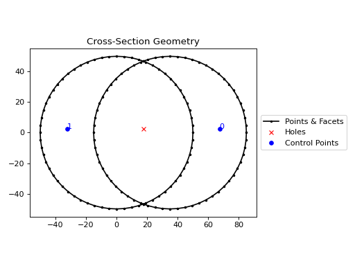
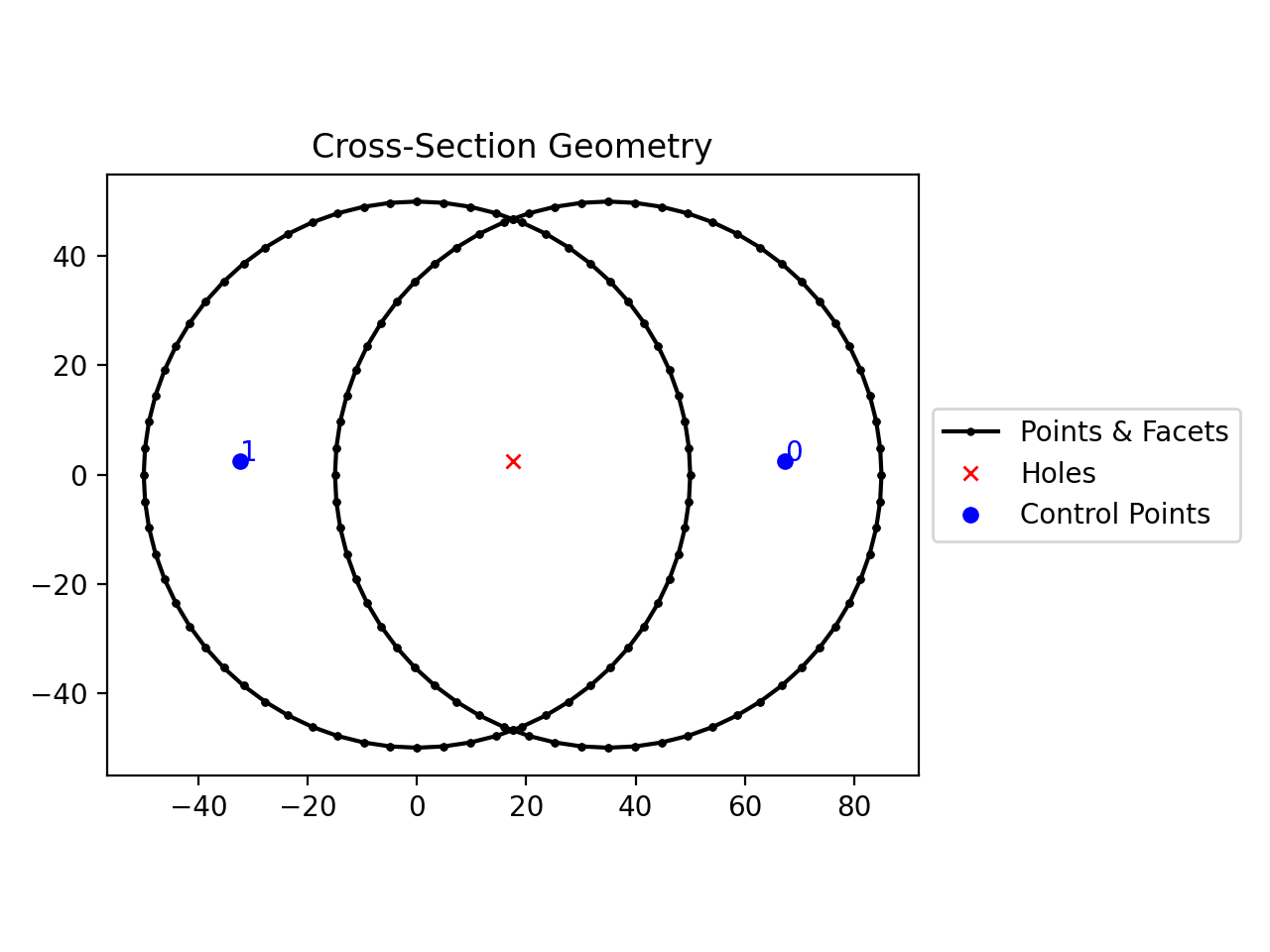
The following example performs a symmetric difference on two circles with the
^operator:from sectionproperties.pre.library import circular_section from sectionproperties.analysis import Section circ1 = circular_section(d=100, n=64) circ2 = circular_section(d=100, n=64).shift_section(x_offset=35) (circ1 ^ circ2).plot_geometry()
(
Source code,png,hires.png,pdf)
Symmetric difference of two circles
+ (Addition)
- Geometry.__add__(other: Geometry | CompoundGeometry) CompoundGeometry[source]
Combine Geometry objects into a CompoundGeometry using the
+operator.- Parameters:
other (Geometry | CompoundGeometry) – Geometry object to perform the combination with
- Raises:
ValueError – Unable to perform combination operation
- Returns:
New Geometry object
- Return type:
Example
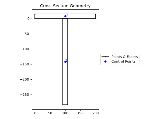
The following example creates a tee section the
+operator:from sectionproperties.pre.library import rectangular_section flange = rectangular_section(d=16, b=200) web = ( rectangular_section(d=284, b=16) .align_center(align_to=flange) .align_to(other=flange, on="bottom") ) (flange + web).plot_geometry()
(
Source code,png,hires.png,pdf)
Tee section
Assigning Material Properties
Each Geometry contains its own material
definition, which is stored in the .material attribute. The simplest way to assign
a material to a Geometry is to pass the
material as an argument to the constructor.
Note
If a Material is not given, then the default
material is assigned to the Geometry.material attribute. The default material
has an elastic modulus of 1, a Poisson’s ratio of 0, a density of 1 and a yield
strength of 1.
This is equivalent to performing a purely geometric analysis of the cross-section and is desirable if a composite section is not being analysed.
Warning
See more about how asssigning material properties affects the results reported by
sectionproperties here.
Below are a few examples showcasing the different ways to generate geometry discussed above:
Example
The following example assigns material properties to a number of different geometries:
from shapely import Polygon

from sectionproperties.pre import Material
from sectionproperties.pre import Geometry
from sectionproperties.pre.library import rectangular_section

# create a steel material
steel = Material(
    name="Steel",
    elastic_modulus=200e3,
    poissons_ratio=0.3,
    density=7.85e-6,
    yield_strength=500,
    color="grey",
)

# assign steel to a shapely generated geometry
poly = Polygon([(0, 0), (5, 2), (3, 7), (1, 6)])
geom = Geometry(geom=poly, material=steel)

# assign steel to a geometry from points
points = [(0, 0), (10, 5), (15, 15), (5, 10), (6, 6), (9, 7), (7, 9)]
facets = [(0, 1), (1, 2), (2, 3), (3, 0), (4, 5), (5, 6), (6, 4)]
control_points = [(4, 4)]
holes = [(7, 7)]
geom = Geometry.from_points(
    points=points,
    facets=facets,
    control_points=control_points,
    holes=holes,
    material=steel,
)

# assign steel to a rectangular section
geom = rectangular_section(d=100, b=50, material=steel)
A geometry’s material may be altered at any time by simply assigning a new
Material to the .material attribute. This is
also useful when creating geometry from CAD files:
Example
The following example demonstrates assigning material properties through changing
the .material attribute.
from sectionproperties.pre import Material
from sectionproperties.pre import Geometry

# create a steel material
steel = Material(
    name="Steel",
    elastic_modulus=200e3,
    poissons_ratio=0.3,
    density=7.85e-6,
    yield_strength=500,
    color="grey",
)

# load 3dm file into a Geometry object
geom = Geometry.from_3dm(filepath="example.3dm")

# assign steel to the geometry
geom.material = steel
A CompoundGeometry does not have a
.material attribute and therefore, a Material
cannot be directly assigned. Since a
CompoundGeometry is simply a combination of
Geometry objects, the material should be
assigned to each individual Geometry object
that make up the CompoundGeometry.
Example
The following example demonstrates assigning material properties to
CompoundGeometry objects.
from shapely import Polygon

from sectionproperties.pre import Material
from sectionproperties.pre.library import rectangular_section
from sectionproperties.analysis import Section

# create steel and timber materials
steel = Material(
    name="Steel",
    elastic_modulus=200e3,
    poissons_ratio=0.3,
    density=7.85e-6,
    yield_strength=500,
    color="grey",
)
timber = Material(
    name="Timber",
    elastic_modulus=8e3,
    poissons_ratio=0.35,
    density=6.5e-7,
    yield_strength=20,
    color="burlywood",
)

# create the individual geometries with material properties applied
beam = rectangular_section(d=170, b=35, material=timber)
plate = rectangular_section(d=16, b=35, material=steel)

# combine geometries, maintaining assigned materials
geom = beam + plate.shift_section(y_offset=-16)

# mesh and plot
geom.create_mesh(mesh_sizes=[20, 10])
Section(geometry=geom).plot_mesh()
(Source code, png, hires.png, pdf)

Assign materials to a CompoundGeometry object
Visualising Geometry
Visualisation of geometry objects is best performed in the Jupyter computing environment, however, most visualisation can also be done in any environment which supports the display of matplotlib plots.
There are generally two ways to visualise geometry objects:
In the Jupyter computing environment, geometry objects utilise their underlying
shapely.geometry.Polygonobject’s_repr_svg_method to show the geometry as it’s own representation.By using the
plot_geometry()method.
- Geometry.plot_geometry(labels: tuple[str] = ('control_points',), title: str = 'Cross-Section Geometry', cp: bool = True, legend: bool = True, **kwargs: Any) matplotlib.axes.Axes[source]
Plots the geometry defined by the input section.
- Parameters:
labels (tuple[str]) – A tuple of str which indicate which labels to plot. Can be one or a combination of
"points","facets","control_points", or an empty tuple to indicate no labels. Defaults to("control_points").title (str) – Plot title. Defaults to
"Cross-Section Geometry".cp (bool) – If set to True, plots the control points. Defaults to
True.legend (bool) – If set to True, plots the legend. Defaults to
True.kwargs (Any) – Passed to
plotting_context()
- Returns:
Matplotlib axes object
- Return type:
Note
You can also use
plot_geometry() with
CompoundGeometry objects