Structure of an Analysis
The process of performing a cross-section analysis with sectionproperties can
be broken down into three stages:
Pre-Processor: The input geometry and finite element mesh is created.
Solver: The cross-section properties are determined.
Post-Processor: The results are presented in a number of different formats.
Creating a Geometry and Mesh
The dimensions and shape of the cross-section to be analysed define the geometry of the cross-section. The Section Library provides a number of functions to easily generate either commonly used structural sections. Alternatively, arbitrary cross-sections can be built from a list of user-defined points, see Geometry from points, facets, holes, and control points.
The final stage in the pre-processor involves generating a finite element mesh of
the geometry that the solver can use to calculate the cross-section properties.
This can easily be performed using the create_mesh()
method that all Geometry objects have
access to.
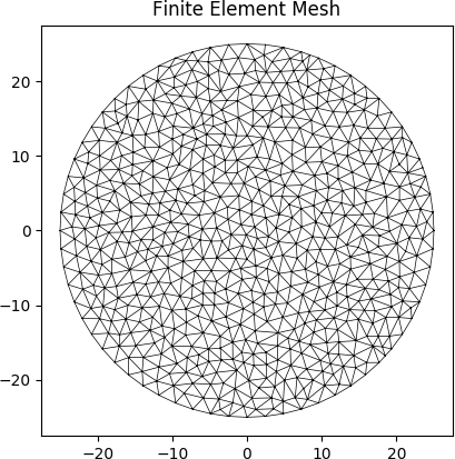
The following example creates a geometry object with a circular cross-section. The diameter of the circle is 50 and 64 points are used to discretise the circumference of the circle. A finite element mesh is generated with a maximum triangular area of 2.5:
import sectionproperties.pre.library.primitive_sections as primitive_sections

geometry = primitive_sections.circular_section(d=50, n=64)
geometry.create_mesh(mesh_sizes=[2.5])

Finite element mesh generated by the above example.
If you are analysing a composite section, or would like to include material properties
in your model, material properties can be created using the Material
class. The following example creates a steel material object:
from sectionproperties.pre.pre import Material

steel = Material(name='Steel', elastic_modulus=200e3, poissons_ratio=0.3, density=7.85e-6,
                 yield_strength=500, color='grey')
Refer to Creating Geometries, Meshes, and Material Properties for a more detailed explanation of the pre-processing stage.
Running an Analysis
The solver operates on a Section
object and can perform four different analysis types:
Geometric Analysis: calculates area properties.
Plastic Analysis: calculates plastic properties.
Warping Analysis: calculates torsion and shear properties.
Stress Analysis: calculates cross-section stresses.
The geometric analysis can be performed individually. However in order to perform a warping or plastic analysis, a geometric analysis must first be performed. Further, in order to carry out a stress analysis, both a geometric and warping analysis must have already been executed. The program will display a helpful error if you try to run any of these analyses without first performing the prerequisite analyses.
The following example performs a geometric and warping analysis on the circular cross-section defined in the previous section with steel used as the material property:
import sectionproperties.pre.library.primitive_sections as primitive_sections
from sectionproperties.analysis.section import Section
from sectionproperties.pre.pre import Material


steel = Material(name='Steel', elastic_modulus=200e3, poissons_ratio=0.3, density=7.85e-6,
                 yield_strength=500, color='grey')
geometry = primitive_sections.circular_section(d=50, n=64, material=steel)
geometry.create_mesh(mesh_sizes=[2.5])  # Adds the mesh to the geometry

section = Section(geometry)
section.calculate_geometric_properties()
section.calculate_warping_properties()
Refer to Running an Analysis for a more detailed explanation of the solver stage.
Viewing the Results
Once an analysis has been performed, a number of methods belonging to the
Section object can be called
to present the cross-section results in a number of different formats. For example
the cross-section properties can be printed to the terminal, a plot of the centroids
displayed and the cross-section stresses visualised in a contour plot.
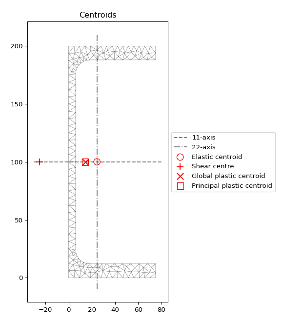
The following example analyses a 200 PFC section. The cross-section properties are printed to the terminal and a plot of the centroids is displayed:
import sectionproperties.pre.library.steel_sections as steel_sections
from sectionproperties.analysis.section import Section

geometry = steel_sections.channel_section(d=200, b=75, t_f=12, t_w=6, r=12, n_r=8)
geometry.create_mesh(mesh_sizes=[2.5])  # Adds the mesh to the geometry

section = Section(geometry)
section.calculate_geometric_properties()
section.calculate_plastic_properties()
section.calculate_warping_properties()

section.plot_centroids()
section.display_results()

Plot of the elastic centroid and shear centre for the above example generated
by plot_centroids()
Output generated by the display_results()
method:
Section Properties:
A       = 2.919699e+03
Perim.  = 6.776201e+02
Qx      = 2.919699e+05
Qy      = 7.122414e+04
cx      = 2.439434e+01
cy      = 1.000000e+02
Ixx_g   = 4.831277e+07
Iyy_g   = 3.392871e+06
Ixy_g   = 7.122414e+06
Ixx_c   = 1.911578e+07
Iyy_c   = 1.655405e+06
Ixy_c   = -6.519258e-09
Zxx+    = 1.911578e+05
Zxx-    = 1.911578e+05
Zyy+    = 3.271186e+04
Zyy-    = 6.786020e+04
rx      = 8.091461e+01
ry      = 2.381130e+01
phi     = 0.000000e+00
I11_c   = 1.911578e+07
I22_c   = 1.655405e+06
Z11+    = 1.911578e+05
Z11-    = 1.911578e+05
Z22+    = 3.271186e+04
Z22-    = 6.786020e+04
r11     = 8.091461e+01
r22     = 2.381130e+01
J       = 1.011522e+05
Iw      = 1.039437e+10
x_se    = -2.505109e+01
y_se    = 1.000000e+02
x_st    = -2.505109e+01
y_st    = 1.000000e+02
x1_se   = -4.944543e+01
y2_se   = 4.905074e-06
A_sx    = 9.468851e+02
A_sy    = 1.106943e+03
A_s11   = 9.468854e+02
A_s22   = 1.106943e+03
betax+  = 1.671593e-05
betax-  = -1.671593e-05
betay+  = -2.013448e+02
betay-  = 2.013448e+02
beta11+ = 1.671593e-05
beta11- = -1.671593e-05
beta22+ = -2.013448e+02
beta22- = 2.013448e+02
x_pc    = 1.425046e+01
y_pc    = 1.000000e+02
Sxx     = 2.210956e+05
Syy     = 5.895923e+04
SF_xx+  = 1.156613e+00
SF_xx-  = 1.156613e+00
SF_yy+  = 1.802381e+00
SF_yy-  = 8.688337e-01
x11_pc  = 1.425046e+01
y22_pc  = 1.000000e+02
S11     = 2.210956e+05
S22     = 5.895923e+04
SF_11+  = 1.156613e+00
SF_11-  = 1.156613e+00
SF_22+  = 1.802381e+00
SF_22-  = 8.688337e-01
Refer to Viewing the Results for a more detailed explanation of the post-processing stage.