Creating Geometries, Meshes, and Material Properties
Before performing a cross-section analysis, the geometry of the cross-section and a finite element mesh must be created. Optionally, material properties can be applied to different regions of the cross-section. If materials are not applied, then a default material is used to report the geometric properties.
Section Geometry
New in v2.0.0 - There are two types of geometry objects in sectionproperties:
The
Geometryclass, for section geometries with a single, contiguous regionThe
CompoundGeometryclass, comprised of two or more Geometry objects
Geometry Class
- class sectionproperties.pre.geometry.Geometry(geom: Polygon, material: pre.Material = Material(name='default', elastic_modulus=1, poissons_ratio=0, yield_strength=1, density=1, color='w'), control_points: Optional[Union[Point, List[float, float]]] = None, tol=12)[source]
Class for defining the geometry of a contiguous section of a single material.
Provides an interface for the user to specify the geometry defining a section. A method is provided for generating a triangular mesh, transforming the section (e.g. translation, rotation, perimeter offset, mirroring), aligning the geometry to another geometry, and designating stress recovery points.
- Variables
geom (
shapely.geometry.Polygon) – a Polygon object that defines the geometrymaterial (Optional[
Material]) – Optional, a Material to associate with this geometrycontrol_point – Optional, an (x, y) coordinate within the geometry that represents a pre-assigned control point (aka, a region identification point) to be used instead of the automatically assigned control point generated with
shapely.geometry.Polygon.representative_point().tol – Optional, default is 12. Number of decimal places to round the geometry vertices to. A lower value may reduce accuracy of geometry but increases precision when aligning geometries to each other.
A Geometry is instantiated with two arguments:
A
shapely.geometry.PolygonobjectAn optional
Materialobject
Note
If a Material is not given, then the default material is
assigned to the Geometry.material attribute. The default material has an elastic modulus of
1, a Poisson’s ratio of 0 and a yield strength of 1.
CompoundGeometry Class
- class sectionproperties.pre.geometry.CompoundGeometry(geoms: Union[MultiPolygon, List[Geometry]])[source]
Class for defining a geometry of multiple distinct regions, each potentially having different material properties.
CompoundGeometry instances are composed of multiple Geometry objects. As with Geometry objects, CompoundGeometry objects have methods for generating a triangular mesh over all geometries, transforming the collection of geometries as though they were one (e.g. translation, rotation, and mirroring), and aligning the CompoundGeometry to another Geometry (or to another CompoundGeometry).
CompoundGeometry objects can be created directly between two or more Geometry objects by using the + operator.
- Variables
geoms (Union[
shapely.geometry.MultiPolygon, List[Geometry]]) – either a list of Geometry objects or ashapely.geometry.MultiPolygoninstance.
A CompoundGeometry is instantiated with one argument
which can be one of two types:
A list of
Geometryobjects; orA
shapely.geometry.MultiPolygon
Note
A CompoundGeometry does not have a .material
attribute and therefore, a Material cannot be assigned to a
CompoundGeometry directly. Since a
CompoundGeometry is simply a combination of
Geometry objects, the Material(s) should be assigned to
the individual Geometry objects that comprise the
CompoundGeometry.
CompoundGeometry objects created from a
shapely.geometry.MultiPolygon will have its constituent
Geometry objects assigned the default material.
Defining Material Properties
Materials are defined in sectionproperties by creating a
Material object:
- class sectionproperties.pre.pre.Material(name: str, elastic_modulus: float, poissons_ratio: float, yield_strength: float, density: float, color: str)[source]
Class for structural materials.
Provides a way of storing material properties related to a specific material. The color can be a multitude of different formats, refer to https://matplotlib.org/api/colors_api.html and https://matplotlib.org/examples/color/named_colors.html for more information.
- Parameters
name (string) – Material name
elastic_modulus (float) – Material modulus of elasticity
poissons_ratio (float) – Material Poisson’s ratio
yield_strength (float) – Material yield strength
density (float) – Material density (mass per unit volume)
color (
matplotlib.colors) – Material color for rendering
- Variables
name (string) – Material name
elastic_modulus (float) – Material modulus of elasticity
poissons_ratio (float) – Material Poisson’s ratio
shear_modulus (float) – Material shear modulus, derived from the elastic modulus and Poisson’s ratio assuming an isotropic material
density (float) – Material density (mass per unit volume)
yield_strength (float) – Material yield strength
color (
matplotlib.colors) – Material color for rendering
The following example creates materials for concrete, steel and timber:
from sectionproperties.pre.pre import Material

concrete = Material(
    name='Concrete', elastic_modulus=30.1e3, poissons_ratio=0.2, density=2.4e-6,
        yield_strength=32, color='lightgrey'
)
steel = Material(
    name='Steel', elastic_modulus=200e3, poissons_ratio=0.3, density=7.85e-6,
        yield_strength=500, color='grey'
)
timber = Material(
    name='Timber', elastic_modulus=8e3, poissons_ratio=0.35, density=6.5e-7,
        yield_strength=20, color='burlywood'
)
Each Geometry contains its own material definition,
which is stored in the .material attribute. A geometry’s material may be altered at any time by
simply assigning a new Material to the .material attribute.
Warning
To understand how material properties affect the results reported by sectionproperties, see How Material Properties Affect Results.
Creating Section Geometries
In addition to creating geometries directly from shapely.geometry.Polygon and/or
shapely.geometry.MultiPolygon objects, there are other ways to create geometries for
analysis:
From lists of points, facets, hole regions, and control regions
From
.dxffilesFrom
.3dmfilesFrom Rhino encodings
Using transformation methods on existing geometries and/or by applying set operations (e.g. |, +, -, &, ^)
From sectionproperties’s section library
For the first two approaches, an optional .material parameter can be passed containing a
Material (or list of Material objects) to associate with the
newly created geometry(ies). The material attribute can be altered afterward in a
Geometry object at any time by simply assigning a
different Material to the .material attribute.
Geometry from points, facets, holes, and control points
In sectionproperties v1.x.x, geometries were created by specifying lists of points, facets,
holes, and control_points. This functionality has been preserved in v2.0.0 by using the
from_points() class method.
- sectionproperties.pre.geometry.Geometry.from_points(points: List[List[float]], facets: List[List[int]], control_points: List[List[float]], holes: Optional[List[List[float]]] = None, material: Optional[Material] = Material(name='default', elastic_modulus=1, poissons_ratio=0, yield_strength=1, density=1, color='w'))
An interface for the creation of Geometry objects through the definition of points, facets, and holes.
- Variables
points (list[list[float, float]]) – List of points (x, y) defining the vertices of the section geometry. If facets are not provided, it is a assumed the that the list of points are ordered around the perimeter, either clockwise or anti-clockwise.
facets (list[list[int, int]]) – A list of (start, end) indexes of vertices defining the edges of the section geoemtry. Can be used to define both external and internal perimeters of holes. Facets are assumed to be described in the order of exterior perimeter, interior perimeter 1, interior perimeter 2, etc.
control_points – An (x, y) coordinate that describes the distinct, contiguous, region of a single material within the geometry. Must be entered as a list of coordinates, e.g. [[0.5, 3.2]] Exactly one point is required for each geometry with a distinct material. If there are multiple distinct regions, then use CompoundGeometry.from_points()
holes (list[list[float, float]]) – Optional. A list of points (x, y) that define interior regions as being holes or voids. The point can be located anywhere within the hole region. Only one point is required per hole region.
material – Optional. A
Materialobject that is to be assigned. If not given, then theDEFAULT_MATERIALwill be used.
For simple geometries (i.e. single-region shapes without holes), if the points are an ordered sequence of coordinates, only the points argument is required (facets, holes, and control_points are optional). If the geometry has holes, then all arguments are required.
If the geometry has multiple regions, then the
from_points() class method must be used.
- sectionproperties.pre.geometry.CompoundGeometry.from_points(points: List[List[float]], facets: List[List[int]], control_points: List[List[float]], holes: Optional[List[List[float]]] = None, materials: Optional[List[Material]] = Material(name='default', elastic_modulus=1, poissons_ratio=0, yield_strength=1, density=1, color='w'))
An interface for the creation of CompoundGeometry objects through the definition of points, facets, holes, and control_points. Geometries created through this method are expected to be non-ambiguous meaning that no “overlapping” geometries exists and that nodal connectivity is maintained (e.g. there are no nodes “overlapping” with facets without nodal connectivity).
- Variables
points (list[list[float]]) – List of points (x, y) defining the vertices of the section geometry. If facets are not provided, it is a assumed the that the list of points are ordered around the perimeter, either clockwise or anti-clockwise
facets (list[list[int]]) – A list of (start, end) indexes of vertices defining the edges of the section geoemtry. Can be used to define both external and internal perimeters of holes. Facets are assumed to be described in the order of exterior perimeter, interior perimeter 1, interior perimeter 2, etc.
control_points (list[list[float]]) – Optional. A list of points (x, y) that define non-interior regions as being distinct, contiguous, and having one material. The point can be located anywhere within region. Only one point is permitted per region. The order of control_points must be given in the same order as the order that polygons are created by ‘facets’. If not given, then points will be assigned automatically using shapely.geometry.Polygon.representative_point()
holes (list[list[float]]) – Optional. A list of points (x, y) that define interior regions as being holes or voids. The point can be located anywhere within the hole region. Only one point is required per hole region.
materials (list[
Material]) – Optional. A list ofMaterialobjects that are to be assigned, in order, to the regions defined by the given control_points. If not given, then theDEFAULT_MATERIALwill be used for each region.
See Creating Custom Geometry for an example of this implementation.
Geometry from .dxf Files
Geometries can now be created from .dxf files using the
sectionproperties.pre.geometry.Geometry.from_dxf() method. The returned geometry will
either be a Geometry or
CompoundGeometry object depending on the geometry in the
file (i.e. the number of contiguous regions).
- sectionproperties.pre.geometry.Geometry.from_dxf(dxf_filepath: Union[str, Path]) Union[Geometry, CompoundGeometry]
An interface for the creation of Geometry objects from CAD .dxf files.
- Variables
dxf_filepath (Union[str, pathlib.Path]) – A path-like object for the dxf file
- sectionproperties.pre.geometry.CompoundGeometry.from_dxf(dxf_filepath: Union[str, Path]) Union[Geometry, CompoundGeometry]
An interface for the creation of Geometry objects from CAD .dxf files.
- Variables
dxf_filepath (Union[str, pathlib.Path]) – A path-like object for the dxf file
Geometry from Rhino
Geometries can now be created from .3dm files and BREP encodings. Various limitations and assumptions need to be acknowledged:
sectional analysis is based in 2d and Rhino is a 3d environment.
the recognised Rhino geometries are limited to planer-single-surfaced BREPs.
Rhino uses NURBS for surface boundaries and sectionproperties uses piecewise linear boundaries.
a search plane is defined.
See the keyword arguments below that are used to search and simplify the Rhino geometry.
Rhino files are read via the class methods sectionproperties.pre.geometry.Geometry.from_3dm() and
sectionproperties.pre.geometry.CompoundGeometry.from_3dm().
Each class method returns the respective objects.
- sectionproperties.pre.geometry.Geometry.from_3dm(filepath: Union[str, Path], **kwargs) Geometry
Class method to create a Geometry from the objects in a Rhino .3dm file.
- Parameters
filepath (Union[str, pathlib.Path]) – File path to the rhino .3dm file.
kwargs – See below.
- Raises
RuntimeError – A RuntimeError is raised if two or more polygons are found. This is dependent on the keyword arguments. Try adjusting the keyword arguments if this error is raised.
- Returns
A Geometry object.
- Return type
- Keyword Arguments
- refine_num (
int, optional) – Bézier curve interpolation number. In Rhino a surface’s edges are nurb based curves. Shapely does not support nurbs, so the individual Bézier curves are interpolated using straight lines. This parameter sets the number of straight lines used in the interpolation. Default is 1.
- refine_num (
- vec1 (
numpy.ndarray, optional) – A 3d vector in the Shapely plane. Rhino is a 3D geometry environment. Shapely is a 2D geometric library. Thus a 2D plane needs to be defined in Rhino that represents the Shapely coordinate system. vec1 represents the 1st vector of this plane. It will be used as Shapely’s x direction. Default is [1,0,0].
- vec1 (
- vec2 (
numpy.ndarray, optional) – Continuing from vec1, vec2 is another vector to define the Shapely plane. It must not be [0,0,0] and it’s only requirement is that it is any vector in the Shapely plane (but not equal to vec1). Default is [0,1,0].
- vec2 (
- plane_distance (
float, optional) – The distance to the Shapely plane. Default is 0.
- plane_distance (
- project (
boolean, optional) – Controls if the breps are projected onto the plane in the direction of the Shapley plane’s normal. Default is True.
- project (
- parallel (
boolean, optional) – Controls if only the rhino surfaces that have the same normal as the Shapely plane are yielded. If true, all non parallel surfaces are filtered out. Default is False.
- parallel (
- sectionproperties.pre.geometry.CompoundGeometry.from_3dm(filepath: Union[str, Path], **kwargs) CompoundGeometry
Class method to create a CompoundGeometry from the objects in a Rhino 3dm file.
- Parameters
filepath (Union[str, pathlib.Path]) – File path to the rhino .3dm file.
kwargs – See below.
- Returns
A CompoundGeometry object.
- Return type
- Keyword Arguments
- refine_num (
int, optional) – Bézier curve interpolation number. In Rhino a surface’s edges are nurb based curves. Shapely does not support nurbs, so the individual Bézier curves are interpolated using straight lines. This parameter sets the number of straight lines used in the interpolation. Default is 1.
- refine_num (
- vec1 (
numpy.ndarray, optional) – A 3d vector in the Shapely plane. Rhino is a 3D geometry environment. Shapely is a 2D geometric library. Thus a 2D plane needs to be defined in Rhino that represents the Shapely coordinate system. vec1 represents the 1st vector of this plane. It will be used as Shapely’s x direction. Default is [1,0,0].
- vec1 (
- vec2 (
numpy.ndarray, optional) – Continuing from vec1, vec2 is another vector to define the Shapely plane. It must not be [0,0,0] and it’s only requirement is that it is any vector in the Shapely plane (but not equal to vec1). Default is [0,1,0].
- vec2 (
- plane_distance (
float, optional) – The distance to the Shapely plane. Default is 0.
- plane_distance (
- project (
boolean, optional) – Controls if the breps are projected onto the plane in the direction of the Shapley plane’s normal. Default is True.
- project (
- parallel (
boolean, optional) – Controls if only the rhino surfaces that have the same normal as the Shapely plane are yielded. If true, all non parallel surfaces are filtered out. Default is False.
- parallel (
Geometry objects can also be created from encodings of Rhino BREP.
- sectionproperties.pre.geometry.Geometry.from_rhino_encoding(r3dm_brep: str, **kwargs) Geometry
Load an encoded single surface planer brep.
- Parameters
r3dm_brep (str) – A Rhino3dm.Brep encoded as a string.
kwargs – See below.
- Returns
A Geometry object found in the encoded string.
- Return type
- Keyword Arguments
- refine_num (
int, optional) – Bézier curve interpolation number. In Rhino a surface’s edges are nurb based curves. Shapely does not support nurbs, so the individual Bézier curves are interpolated using straight lines. This parameter sets the number of straight lines used in the interpolation. Default is 1.
- refine_num (
- vec1 (
numpy.ndarray, optional) – A 3d vector in the Shapely plane. Rhino is a 3D geometry environment. Shapely is a 2D geometric library. Thus a 2D plane needs to be defined in Rhino that represents the Shapely coordinate system. vec1 represents the 1st vector of this plane. It will be used as Shapely’s x direction. Default is [1,0,0].
- vec1 (
- vec2 (
numpy.ndarray, optional) – Continuing from vec1, vec2 is another vector to define the Shapely plane. It must not be [0,0,0] and it’s only requirement is that it is any vector in the Shapely plane (but not equal to vec1). Default is [0,1,0].
- vec2 (
- plane_distance (
float, optional) – The distance to the Shapely plane. Default is 0.
- plane_distance (
- project (
boolean, optional) – Controls if the breps are projected onto the plane in the direction of the Shapley plane’s normal. Default is True.
- project (
- parallel (
boolean, optional) – Controls if only the rhino surfaces that have the same normal as the Shapely plane are yielded. If true, all non parallel surfaces are filtered out. Default is False.
- parallel (
More advanced filtering can be achieved by working with the Shapely geometries directly.
These can be accessed by load_3dm() and
load_rhino_brep_encoding().
- sectionproperties.pre.rhino.load_3dm(r3dm_filepath: Union[Path, str], **kwargs) List[Polygon][source]
Load a Rhino .3dm file and import the single surface planer breps.
- Parameters
r3dm_filepath (pathlib.Path or string) – File path to the rhino .3dm file.
kwargs – See below.
- Raises
RuntimeError – A RuntimeError is raised if no polygons are found in the file. This is dependent on the keyword arguments. Try adjusting the keyword arguments if this error is raised.
- Returns
List of Polygons found in the file.
- Return type
List[shapely.geometry.Polygon]
- Keyword Arguments
- refine_num (
int, optional) – Bézier curve interpolation number. In Rhino a surface’s edges are nurb based curves. Shapely does not support nurbs, so the individual Bézier curves are interpolated using straight lines. This parameter sets the number of straight lines used in the interpolation. Default is 1.
- refine_num (
- vec1 (
numpy.ndarray, optional) – A 3d vector in the Shapely plane. Rhino is a 3D geometry environment. Shapely is a 2D geometric library. Thus a 2D plane needs to be defined in Rhino that represents the Shapely coordinate system. vec1 represents the 1st vector of this plane. It will be used as Shapely’s x direction. Default is [1,0,0].
- vec1 (
- vec2 (
numpy.ndarray, optional) – Continuing from vec1, vec2 is another vector to define the Shapely plane. It must not be [0,0,0] and it’s only requirement is that it is any vector in the Shapely plane (but not equal to vec1). Default is [0,1,0].
- vec2 (
- plane_distance (
float, optional) – The distance to the Shapely plane. Default is 0.
- plane_distance (
- project (
boolean, optional) – Controls if the breps are projected onto the plane in the direction of the Shapley plane’s normal. Default is True.
- project (
- parallel (
boolean, optional) – Controls if only the rhino surfaces that have the same normal as the Shapely plane are yielded. If true, all non parallel surfaces are filtered out. Default is False.
- parallel (
- sectionproperties.pre.rhino.load_brep_encoding(brep: str, **kwargs) Polygon[source]
Load an encoded single surface planer brep.
- Parameters
brep (str) – Rhino3dm.Brep encoded as a string.
kwargs – See below.
- Raises
RuntimeError – A RuntimeError is raised if no polygons are found in the encoding. This is dependent on the keyword arguments. Try adjusting the keyword arguments if this error is raised.
- Returns
The Polygons found in the encoding string.
- Return type
shapely.geometry.Polygon
- Keyword Arguments
- refine_num (
int, optional) – Bézier curve interpolation number. In Rhino a surface’s edges are nurb based curves. Shapely does not support nurbs, so the individual Bézier curves are interpolated using straight lines. This parameter sets the number of straight lines used in the interpolation. Default is 1.
- refine_num (
- vec1 (
numpy.ndarray, optional) – A 3d vector in the Shapely plane. Rhino is a 3D geometry environment. Shapely is a 2D geometric library. Thus a 2D plane needs to be defined in Rhino that represents the Shapely coordinate system. vec1 represents the 1st vector of this plane. It will be used as Shapely’s x direction. Default is [1,0,0].
- vec1 (
- vec2 (
numpy.ndarray, optional) – Continuing from vec1, vec2 is another vector to define the Shapely plane. It must not be [0,0,0] and it’s only requirement is that it is any vector in the Shapely plane (but not equal to vec1). Default is [0,1,0].
- vec2 (
- plane_distance (
float, optional) – The distance to the Shapely plane. Default is 0.
- plane_distance (
- project (
boolean, optional) – Controls if the breps are projected onto the plane in the direction of the Shapley plane’s normal. Default is True.
- project (
- parallel (
boolean, optional) – Controls if only the rhino surfaces that have the same normal as the Shapely plane are yielded. If true, all non parallel surfaces are filtered out. Default is False.
- parallel (
Note
Dependencies for importing files from rhino are not included by default. To obtain the required dependencies install sectionproperties with the rhino option:
pip install sectionproperties[rhino]
Combining Geometries Using Set Operations
Both Geometry and CompoundGeometry objects can be manipulated using Python’s set operators:
|Bitwise OR - Performs a union on the two geometries-Bitwise DIFFERENCE - Performs a subtraction, subtracting the second geometry from the first&Bitwise AND - Performs an intersection operation, returning the regions of geometry common to both^Bitwise XOR - Performs a symmetric difference operation, returning the regions of geometry that are not overlapping+Addition - Combines two geometries into a CompoundGeometry
See Advanced Geometry Creation for an example using set operations.
sectionproperties Section Library
Manipulating Geometries
Each geometry instance is able to be manipulated in 2D space for the purpose of creating novel, custom section geometries that the user may require.
Note
Operations on geometries are non-destructive. For each operation, a new geometry object is returned.
This gives sectionproperties geoemtries a fluent API meaning that transformation methods can be chained together. Please see Advanced Geometry Creation for examples.
Aligning
- sectionproperties.pre.geometry.Geometry.align_center(self, align_to: Optional[Union[Geometry, Tuple[float, float]]] = None)
Returns a new Geometry object, translated in both x and y, so that the the new object’s centroid will be aligned with the centroid of the object in ‘align_to’. If ‘align_to’ is an x, y coordinate, then the centroid will be aligned to the coordinate. If ‘align_to’ is None then the new object will be aligned with its centroid at the origin.
- sectionproperties.pre.geometry.Geometry.align_to(self, other: Union[Geometry, Tuple[float, float]], on: str, inner: bool = False) Geometry
Returns a new Geometry object, representing ‘self’ translated so that is aligned ‘on’ one of the outer bounding box edges of ‘other’.
If ‘other’ is a tuple representing an (x,y) coordinate, then the new Geometry object will represent ‘self’ translated so that it is aligned ‘on’ that side of the point.
- Parameters
other (Union[
Geometry, Tuple[float, float]]) – Either another Geometry or a tuple representing an (x,y) coordinate point that ‘self’ should align to.on – A str of either “left”, “right”, “bottom”, or “top” indicating which side of ‘other’ that self should be aligned to.
inner (bool) – Default False. If True, align ‘self’ to ‘other’ in such a way that ‘self’ is aligned to the “inside” of ‘other’. In other words, align ‘self’ to ‘other’ on the specified edge so they overlap.
- Returns
Geometry object translated to alignment location
- Return type
Mirroring
- sectionproperties.pre.geometry.Geometry.mirror_section(self, axis: str = 'x', mirror_point: Union[List[float], str] = 'center')
Mirrors the geometry about a point on either the x or y-axis.
- Parameters
axis (string) – Axis about which to mirror the geometry, ‘x’ or ‘y’
mirror_point (Union[list[float, float], str]) – Point about which to mirror the geometry (x, y). If no point is provided, mirrors the geometry about the centroid of the shape’s bounding box. Default = ‘center’.
- Returns
New Geometry-object mirrored on ‘axis’ about ‘mirror_point’
- Return type
The following example mirrors a 200PFC section about the y-axis and the point (0, 0):
import sectionproperties.pre.library.steel_sections as steel_sections

geometry = steel_sections.channel_section(d=200, b=75, t_f=12, t_w=6, r=12, n_r=8)
new_geometry = geometry.mirror_section(axis='y', mirror_point=[0, 0])
Rotating
- sectionproperties.pre.geometry.Geometry.rotate_section(self, angle: float, rot_point: Union[List[float], str] = 'center', use_radians: bool = False)
Rotates the geometry and specified angle about a point. If the rotation point is not provided, rotates the section about the center of the geometry’s bounding box.
- Parameters
angle (float) – Angle (degrees by default) by which to rotate the section. A positive angle leads to a counter-clockwise rotation.
rot_point (list[float, float]) – Optional. Point (x, y) about which to rotate the section. If not provided, will rotate about the center of the geometry’s bounding box. Default = ‘center’.
use_radians – Boolean to indicate whether ‘angle’ is in degrees or radians. If True, ‘angle’ is interpreted as radians.
- Returns
New Geometry-object rotated by ‘angle’ about ‘rot_point’
- Return type
The following example rotates a 200UB25 section clockwise by 30 degrees:
import sectionproperties.pre.library.steel_sections as steel_sections

geometry = steel_sections.i_section(d=203, b=133, t_f=7.8, t_w=5.8, r=8.9, n_r=8)
new_geometry = geometry.rotate_section(angle=-30)
Shifting
- sectionproperties.pre.geometry.Geometry.shift_points(self, point_idxs: Union[int, List[int]], dx: float = 0, dy: float = 0, abs_x: Optional[float] = None, abs_y: Optional[float] = None) Geometry
Translates one (or many points) in the geometry by either a relative amount or to a new absolute location. Returns a new Geometry representing the original with the selected point(s) shifted to the new location.
Points are identified by their index, their relative location within the points list found in
self.points. You can callself.plot_geometry(labels="points")to see a plot with the points labeled to find the appropriate point indexes.
- Parameters
point_idxs (Union[int, List[int]]) – An integer representing an index location or a list of integer index locations.
dx (float) – The number of units in the x-direction to shift the point(s) by
dy (float) – The number of units in the y-direction to shift the point(s) by
abs_x (Optional[float]) – Absolute x-coordinate in coordinate system to shift the point(s) to. If abs_x is provided, dx is ignored. If providing a list to point_idxs, all points will be moved to this absolute location.
abs_y (Optional[float]) – Absolute y-coordinate in coordinate system to shift the point(s) to. If abs_y is provided, dy is ignored. If providing a list to point_idxs, all points will be moved to this absolute location.
- Returns
Geometry object with selected points translated to the new location.
- Return type
The following example expands the sides of a rectangle, one point at a time, to make it a square:
import sectionproperties.pre.library.primitive_sections as primitive_sections

geometry = primitive_sections.rectangular_section(d=200, b=150)

# Using relative shifting
one_pt_shifted_geom = geometry.shift_points(point_idxs=1, dx=50)

# Using absolute relocation
both_pts_shift_geom = one_pt_shift_geom.shift_points(point_idxs=2, abs_x=200)
- sectionproperties.pre.geometry.Geometry.shift_section(self, x_offset=0.0, y_offset=0.0)
Returns a new Geometry object translated by ‘x_offset’ and ‘y_offset’.
- Parameters
x_offset (float) – Distance in x-direction by which to shift the geometry.
y_offset (float) – Distance in y-direction by which to shift the geometry.
- Returns
New Geometry-object shifted by ‘x_offset’ and ‘y_offset’
- Return type
Splitting
- sectionproperties.pre.geometry.Geometry.split_section(self, point_i: Tuple[float, float], point_j: Optional[Tuple[float, float]] = None, vector: Union[Tuple[float, float], None, ndarray] = None) Tuple[List[Geometry], List[Geometry]]
Splits, or bisects, the geometry about a line, as defined by two points on the line or by one point on the line and a vector. Either
point_jorvectormust be given. Ifpoint_jis given,vectoris ignored.Returns a tuple of two lists each containing new Geometry instances representing the “top” and “bottom” portions, respectively, of the bisected geometry.
If the line is a vertical line then the “right” and “left” portions, respectively, are returned.
- Parameters
point_i (Tuple[float, float]) – A tuple of (x, y) coordinates to define a first point on the line
point_j (Tuple[float, float]) – Optional. A tuple of (x, y) coordinates to define a second point on the line
vector (Union[Tuple[float, float], numpy.ndarray]) – Optional. A tuple or numpy ndarray of (x, y) components to define the line direction.
- Returns
A tuple of lists containing Geometry objects that are bisected about the line defined by the two given points. The first item in the tuple represents the geometries on the “top” of the line (or to the “right” of the line, if vertical) and the second item represents the geometries to the “bottom” of the line (or to the “left” of the line, if vertical).
- Return type
The following example splits a 200PFC section about the y-axis:
import sectionproperties.pre.library.steel_sections as steel_sections
from shapely import LineString

geometry = steel_sections.channel_section(d=200, b=75, t_f=12, t_w=6, r=12, n_r=8)
right_geom, left_geom = geometry.split_section((0, 0), (0, 1))
Offsetting the Perimeter
- sectionproperties.pre.geometry.Geometry.offset_perimeter(self, amount: float = 0, where: str = 'exterior', resolution: float = 12)
Dilates or erodes the section perimeter by a discrete amount.
- Parameters
amount (float) – Distance to offset the section by. A -ve value “erodes” the section. A +ve value “dilates” the section.
where (str) – One of either “exterior”, “interior”, or “all” to specify which edges of the geometry to offset. If geometry has no interiors, then this parameter has no effect. Default is “exterior”.
resolution (float) – Number of segments used to approximate a quarter circle around a point
- Returns
Geometry object translated to new alignment
- Return type
The following example erodes a 200PFC section by 2 mm:
import sectionproperties.pre.library.steel_sections as steel_sections

geometry = sections.channel_section(d=200, b=75, t_f=12, t_w=6, r=12, n_r=8)
new_geometry = geometry.offset_perimeter(amount=-2)
- sectionproperties.pre.geometry.CompoundGeometry.offset_perimeter(self, amount: float = 0, where='exterior', resolution: float = 12)
Dilates or erodes the perimeter of a CompoundGeometry object by a discrete amount.
- Parameters
amount (float) – Distance to offset the section by. A -ve value “erodes” the section. A +ve value “dilates” the section.
where (str) – One of either “exterior”, “interior”, or “all” to specify which edges of the geometry to offset. If geometry has no interiors, then this parameter has no effect. Default is “exterior”.
resolution (float) – Number of segments used to approximate a quarter circle around a point
- Returns
Geometry object translated to new alignment
- Return type
The following example erodes a 200UB25 with a 12 plate stiffener section by 2 mm:
import sectionproperties.pre.library.steel_sections as steel_sections
import sectionproperties.pre.library.primitive_sections as primitive_sections

geometry_1 = steel_sections.i_section(d=203, b=133, t_f=7.8, t_w=5.8, r=8.9, n_r=8)
geometry_2 = primitive_sections.rectangular_section(d=12, b=133)
compound = geometry_2.align_center(geometry_1).align_to(geometry_1, on="top") + geometry_1
new_geometry = compound.offset_perimeter(amount=-2)
Note
If performing a positive offset on a CompoundGeometry with multiple materials, ensure that the materials propagate as desired by performing a .plot_mesh() prior to performing any analysis.
Visualising the Geometry
Visualisation of geometry objects is best performed in the Jupyter computing environment, however, most visualisation can also be done in any environment which supports display of matplotlib plots.
There are generally two ways to visualise geometry objects:
In the Jupyter computing environment, geometry objects utilise their underlying
shapely.geometry.Polygonobject’s_repr_svg_method to show the geometry as it’s own representation.By using the
plot_geometry()method
- Geometry.plot_geometry(labels=['control_points'], title='Cross-Section Geometry', cp=True, legend=True, **kwargs)[source]
Plots the geometry defined by the input section.
- Parameters
labels (list[str]) – A list of str which indicate which labels to plot. Can be one or a combination of “points”, “facets”, “control_points”, or an empty list to indicate no labels. Default is [“control_points”]
title (string) – Plot title
cp (bool) – If set to True, plots the control points
legend (bool) – If set to True, plots the legend
kwargs – Passed to
plotting_context()
- Returns
Matplotlib axes object
- Return type
matplotlib.axes
The following example creates a CHS discretised with 64 points, with a diameter of 48 and thickness of 3.2, and plots the geometry:
import sectionproperties.pre.library.steel_sections as steel_sections

geometry = steel_sections.circular_hollow_section(d=48, t=3.2, n=64)
geometry.plot_geometry()
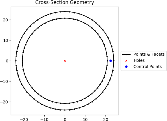
Geometry generated by the above example.
Note
You can also use .plot_geometry() with CompoundGeometry objects
Generating a Mesh
A finite element mesh is required to perform a cross-section analysis. After a geometry has been
created, a finite element mesh can then be created for the geometry by using the
create_mesh() method:
- Geometry.create_mesh(mesh_sizes: Union[float, List[float]], coarse: bool = False)[source]
Creates a quadratic triangular mesh from the Geometry object.
- Parameters
mesh_sizes (Union[float, List[float]]) – A float describing the maximum mesh element area to be used within the Geometry-object finite-element mesh.
coarse (bool) – If set to True, will create a coarse mesh (no area or quality constraints)
- Returns
Geometry-object with mesh data stored in .mesh attribute. Returned Geometry-object is self, not a new instance.
- Return type
The following example creates a circular cross-section with a diameter of 50 with 64 points, and generates a mesh with a maximum triangular area of 2.5:
import sectionproperties.pre.library.primitive_sections as primitive_sections

geometry = primitive_sections.circular_section(d=50, n=64)
geometry = geometry.create_mesh(mesh_sizes=2.5)
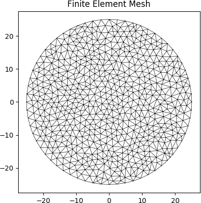
Mesh generated from the above geometry.
Warning
The length of mesh_sizes must match the number of regions
in the geometry object.
Once the mesh has been created, it is stored within the geometry object and the geometry object
can then be passed to Section for analysis.
Please see Running an Analysis for further information on performing analyses.